
A drilling fluid analysis device and analysis method thereof

An analysis device and analysis method technology, applied in the direction of material excitation analysis, Raman scattering, etc., can solve the problems affecting the stability and reliability of gas chromatographic analysis, complex gas circuit system of gas chromatographic analysis equipment, high failure rate, etc., to achieve The effect of high accuracy, low cost, and low failure rate

Active Publication Date: 2015-08-12
SHANGHAI SHENKAI GASOLINEEUM TECH +2
View PDF6 Cites 0 Cited by
  • Summary
  • Abstract
  • Description
  • Claims
  • Application Information

AI Technical Summary

Problems solved by technology

The main disadvantages of gas chromatography analysis are: (1) The drilling fluid samples to be tested need to be degassed and separated, the operation steps are complicated, and a series of auxiliary production equipment such as air compressors and hydrogen generators are required, and the cost is high; (2) The gas circuit system of the degassing separation treatment equipment and gas chromatographic analysis equipment is relatively complex, the detection speed is slow, and the failure rate is high; (3) In the process of degassing and separating the drilling fluid, the degassing efficiency The instability of the gas sample transmission line and the temperature of the gas sample transmission line have a direct impact on the detection results, affecting the stability and reliability of the gas chromatographic analysis

Method used


Image

  • A drilling fluid analysis device and analysis method thereof
  • A drilling fluid analysis device and analysis method thereof
  • A drilling fluid analysis device and analysis method thereof

Examples


Embodiment Construction

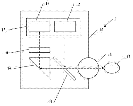
[0033] The present invention will be further elaborated below by describing a preferred specific embodiment in detail in conjunction with the accompanying drawings.

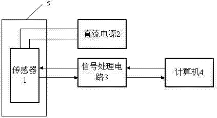
[0034] See attached figure 2 As shown, a drilling fluid analysis device of the present invention includes: a sensor 1 , a DC power supply 2 , a signal processing circuit 3 , and a computer 4 . The DC power supply 2 is connected with the sensor 1 to provide working power; the signal processing circuit 3 is connected with the sensor 1 and the computer 4 respectively; the sensor 1 outputs an analog electrical signal and sends it to the signal processing circuit 3, and the signal processing circuit 3 simulates the analog electrical signal The digital conversion makes it into a Raman digital signal and sends it to the computer 4. The computer 4 processes the received Raman digital signal, and bidirectionally transmits the control signal and data through the signal processing circuit 3 and the sensor 1.

[0035] The se...


PUM


Abstract

The invention discloses a drilling fluid analysis device and method. The drilling fluid analysis device comprises a computer, a sensor, a direct current power supply and a signal processing circuit, wherein the direct current power supply is connected with the sensor and supplies working power to the sensor; and the signal processing circuit is connected with the sensor and the computer respectively. The drilling fluid analysis method comprises the following steps of: arranging the sensor in a drilling fluid tank; emitting Raman excitation light by the sensor to a tested sample; receiving the Raman excitation light sent by the tested sample; converting a light signal of the Raman excitation light into an analog electric signal, sending the analog electric signal to the signal processing circuit, performing digital-to-analog conversion to obtain a Raman digital signal; then sending the Raman digital signal to the computer for analysis calculation through the signal processing circuit; and calculating the concentration of hydrocarbon substances in the tested sample by using a relational expression of the Raman scattered light and the concentration of the tested sample. By the drilling fluid analysis device and the drilling fluid analysis method, drilling fluid can be directly and quantitatively analyzed in real time; the detection speed is high; the analysis accuracy is high; and the device is simple in structure, stable in performance and relatively low in cost.

Description

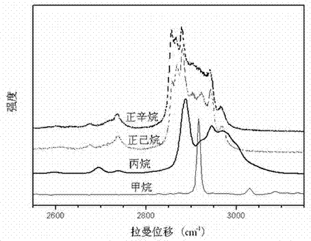
technical field [0001] The invention relates to a drilling fluid analysis device, in particular to a drilling fluid analysis device and an analysis method based on Raman spectrum analysis. Background technique [0002] During the collision process of photons and molecules, in addition to being absorbed by molecules, scattering will also occur. Due to the different ways of collision, there will be multiple forms of scattering between photons and molecules (elastic and inelastic collisions). If there is an energy exchange between the photon and the molecule when they collide, this not only changes the photon's direction of motion, but also its energy. This scattering is called Raman scattering in the spectrum, and its intensity is about 10 times that of the incident ray. -7 . This was discovered by Indian physicist Raman in 1928 when he studied the light scattering of benzene, and won the 1930 Nobel Prize in Physics for this. [0003] Since Raman scattering mainly involves ...

Claims


Application Information

Patent Timeline
IPC IPC(8): G01N21/65
Inventor 赵要强郑周俊陈勇
Owner SHANGHAI SHENKAI GASOLINEEUM TECH
Learn More