Check patentability & draft patents in minutes with Patsnap Eureka AI!

Zero control structure for magnetic resistance of spin valve

A control structure and spin valve technology, applied in the direction of measuring magnetic variables, measuring devices, instruments, etc., can solve the problem of low magnetic field sensitivity, achieve the effect of reducing the random drift of voltage zero position and reducing magnetic stickiness

Inactive Publication Date: 2013-02-27
710TH RES INST OF CHINA SHIPBUILDING IND CORP
View PDF3 Cites 0 Cited by
  • Summary
  • Abstract
  • Description
  • Claims
  • Application Information

AI Technical Summary

Problems solved by technology

This device can meet the requirements when used in a lower frequency magnetic field, but it cannot be used when the magnetic field frequency is higher, and the magnetic field sensitivity is not very high

Method used


Image

  • Zero control structure for magnetic resistance of spin valve
  • Zero control structure for magnetic resistance of spin valve
  • Zero control structure for magnetic resistance of spin valve

Examples


Embodiment Construction

[0021] Below by embodiment, the present invention is further described.

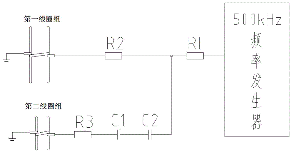
[0022] figure 1 It is a schematic diagram of the coil scanning magnetic field circuit of the present invention, and R1-R3, C1, C2 represent the resistance and capacitance values ​​of the coil group and the circuit. A 500KHz signal is generated by a frequency generator, and a magnetic field with a magnetic induction amplitude of 80nT is generated in the first coil group. The second coil group passes through capacitors C1 and C2 to generate a phase shift of 90° and a magnetic induction amplitude of 80nT. frequency magnetic field.

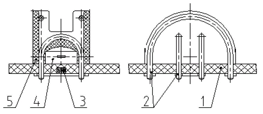
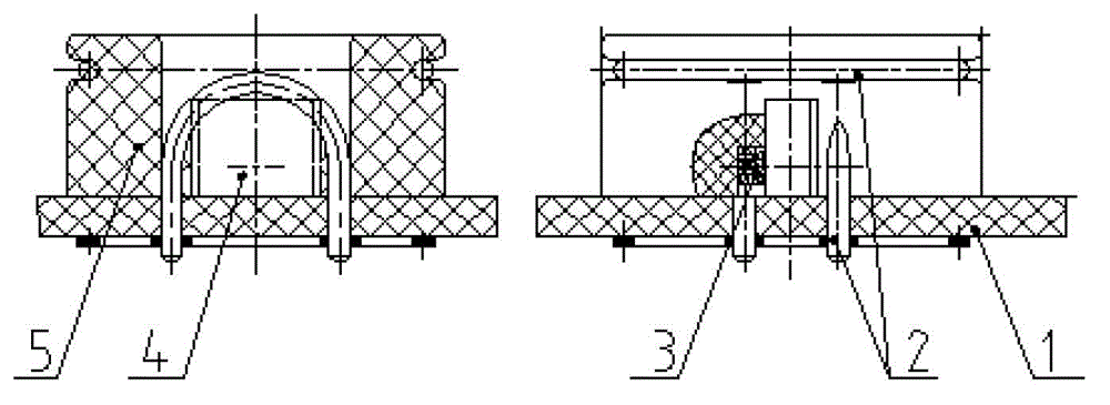
[0023] figure 2 and image 3 is the structural principle diagram of the spin valve magnetoresistive zero position control device of the present invention, wherein figure 2 SOP8, STO-23 packages for spin valve magnetoresistance, image 3 It is packaged in TO-94 form. The spin valve reluctance zero position control device is assembled by a printed circuit board 1 , an alte...


PUM


Abstract

The invention relates to a zero control structure for magnetic resistance of a spin valve, which belongs to the field of flux weakening vector measurement. The control structure adopts an installation manner that a permanent magnet and one or two magneto-resistive element(s) of the spin valve is / are arranged on a printed circuit board, and the axis in the length direction of the permanent magnet is perpendicular to the magneto-sensitive direction of the magneto-resistive element of the spin valve; an alternating magnetic field coil is arranged on the printed circuit board through a coil frame; and the one or two magneto-resistive element(s) of the spin valve is / are arranged at the center of the alternating magnetic field coil, and the axes of a first coil group and a second coil group are parallel to or perpendicular to the magneto-sensitive direction of each magneto-resistive element of the spin valve. According to the control structure, the polarized permanent magnet and a high-frequency weak magnet field act on a shielding layer of a magneto-resistive sensor of the spin valve, so that the discreteness of differential permeability is less, and furthermore, the random zero drift of voltage of the magneto-resistive element of the spin valve is alleviated.

Description

technical field [0001] The invention relates to a spin valve reluctance zero control structure, which belongs to the field of magnetic vector measurement. Background technique [0002] The magnetic measurement range of the spin valve (or tunnel) magnetoresistive device is much smaller than that of the Hall magnetic element, which is suitable for the measurement of weaker magnetic fields and has higher sensitivity. According to the literature reports and the actual situation, compared with the fluxgate sensor, the performance index of the spin valve magnetoresistive device is on an order of magnitude. In comparison, fluxgate sensors have high technical requirements, low frequency response, and relatively large mass and volume. The spin valve magnetoresistive device is small in size and light in weight, and has a high frequency response. However, due to the structural characteristics of the micro-magnetoelectric film layer of the magnetoresistive sensor, there is a large ran...

Claims


Application Information

Patent Timeline
IPC IPC(8): G01R33/09
Inventor 佘以军车振黄春奎李伟
Owner 710TH RES INST OF CHINA SHIPBUILDING IND CORP
Features
  • R&D
  • Intellectual Property
  • Life Sciences
  • Materials
  • Tech Scout
  • Unparalleled Data Quality
  • Higher Quality Content
  • 60% Fewer Hallucinations
Learn More