
AC-DC (Alternating Current-Direct Current) regulator and regulating method

A regulator and flip-flop technology, applied in the direction of irreversible AC power input conversion to DC power output, etc., can solve the problems of inductive current peak deviation, inductive current final peak value and target peak value error, constant current output value difference, etc. , to achieve the effect of eliminating nonlinear error, eliminating turn-off delay error, and high-precision constant current output

Active Publication Date: 2013-02-27
WUXI ZGMICRO ELECTRONICS CO LTD
View PDF6 Cites 4 Cited by
  • Summary
  • Abstract
  • Description
  • Claims
  • Application Information

AI Technical Summary

Problems solved by technology

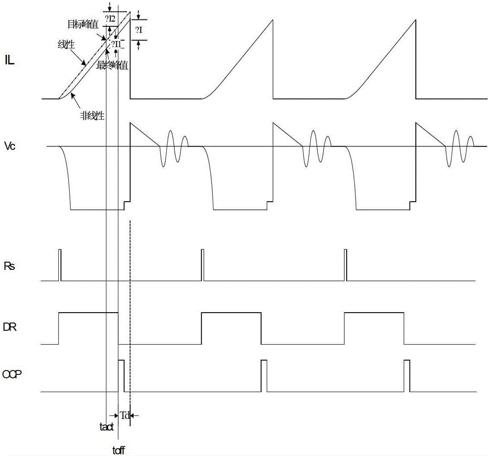
[0006] Non-linearity and turn-off delay time cause the actual peak inductor current to deviate from the target (or ideal) peak value of the inductor current, as image 3 ΔI in
[0007] The disadvantage of the existing solution is the nonlinear characteristic of the inductor current, and the inductor current will continue to rise after the power tube is turned off. These two factors lead to an error between the final peak value of the inductor current and the target peak value. At the same time, these two factors are also related to the system. Parasitic correlation, which eventually leads to large differences in constant current output values ​​​​between products

Method used


Image

  • AC-DC (Alternating Current-Direct Current) regulator and regulating method
  • AC-DC (Alternating Current-Direct Current) regulator and regulating method
  • AC-DC (Alternating Current-Direct Current) regulator and regulating method

Examples


Embodiment Construction

[0027] The technical solutions of the embodiments of the present invention will be further described in detail below through the accompanying drawings and embodiments.

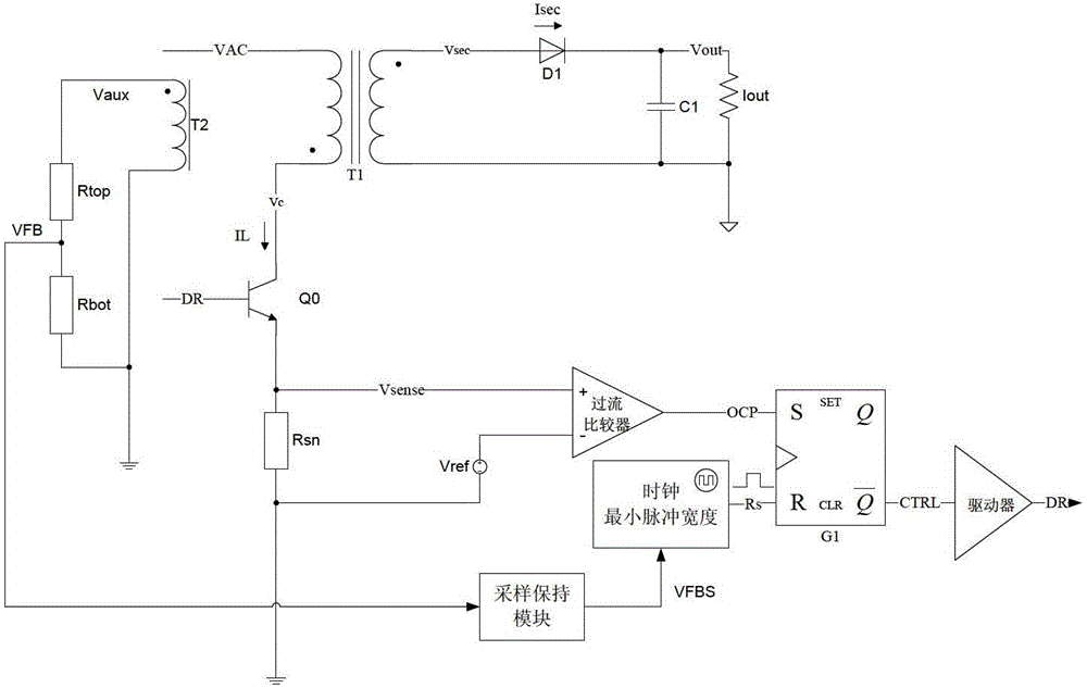
[0028] Figure 4 It is a schematic diagram of an AC-DC regulator in an embodiment of the present invention. Such as Figure 4 As shown, the AC-DC circuit has a transformer T1 between the input VAC and the output Vout, and the transformer T1 functions as an electrical isolation.

[0029] The rectified voltage VAC of the AC voltage is applied to one end of the main winding of the transformer T1, and the other end of the main winding is grounded through the power tube Q0 and the resistance Rsn. An over-current comparator detects whether the voltage on both sides of the resistor Rsn is greater than the reference voltage Vref, and generates an OCP signal based on the detection. The OCP signal is input to the S input of the RS flip-flop to generate a set CTRL signal. The RS flip-flop can also reset the CTRL signal unde...


PUM


Abstract

The embodiment of the invention relates to an AC-DC (Alternating Current-Direct Current) regulator and a regulating method. The AC-DC regulator comprises a transformer and a power tube connected to the main winding side of the transformer, wherein when a voltage corresponding to the current of a main winding is higher than a reference voltage, the grid electrode of the power tube is controlled to be switched off. The AC-DC regulator is characterized by also comprising an integrator, a delay lock ring and a reference voltage regulating circuit, wherein the integrator is used for carrying out first integration on a first auxiliary current coupled by the current of the main winding to obtain a first integration increment, carrying out secondary integration on a second auxiliary current coupled by the current of the main winding within a third duration corresponding to a reference current to obtain a second integration increment, and obtaining a second duration of expecting to raise the current of the main winding to a target current peak on the basis of the first integration increment and the second integration increment; the delay lock ring is used for comparing the first duration of raising the current of the main winding to the peak with the second duration of expecting to raise the current of the winding to the target current peak; and the reference voltage regulating circuit is used for regulating the reference voltage by using a comparing result. According to the invention, the time difference is zero, parasitic switching-off delay errors are eliminated and high-precision constant-current output among products is realized.

Description

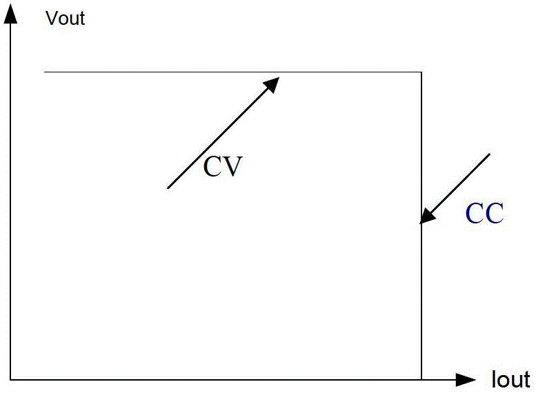
Technical field [0001] The invention relates to the field of power management, in particular to an AC-DC regulator. Background technique [0002] In flyback AC-DC AC-DC applications, it is sometimes necessary to achieve the secondary output with constant voltage and constant current (CV / CC) characteristics, figure 1 It is a schematic diagram of constant voltage and constant current output curve. Constant voltage generally samples the secondary output voltage or indirectly samples the secondary output voltage, which is achieved through negative feedback adjustment; while constant current is generally achieved by setting the peak value of the inductor current of the main winding, that is, Iout=K*Ipeak 2 , Where Iout is the magnitude of the secondary output constant current, Ipeak is the peak current of the main winding, K is the gain coefficient, the unit is A -1 . [0003] figure 2 It is a schematic diagram of the current technology to achieve constant current. image 3 Yes figure...

Claims


Application Information

Patent Timeline
Patent Type & Authority Applications(China)
IPC IPC(8): H02M7/12
Inventor 王才宝王钊
Owner WUXI ZGMICRO ELECTRONICS CO LTD
Learn More