Hydrodynamic retarder and method for operating a hydrodynamic retarder

A technology of hydraulic reducer and reducer, which is applied in the field of hydraulic reducer, can solve problems such as inability to monitor the reducer, and achieve the effect of simple structure, simple replacement and maintenance

Active Publication Date: 2013-02-27
VOITH PATENT GMBH
View PDF6 Cites 23 Cited by
  • Summary
  • Abstract
  • Description
  • Claims
  • Application Information

AI Technical Summary

Problems solved by technology

Therefore, further monitoring of the gear unit i

Method used


Image

  • Hydrodynamic retarder and method for operating a hydrodynamic retarder
  • Hydrodynamic retarder and method for operating a hydrodynamic retarder

Examples


Embodiment Construction

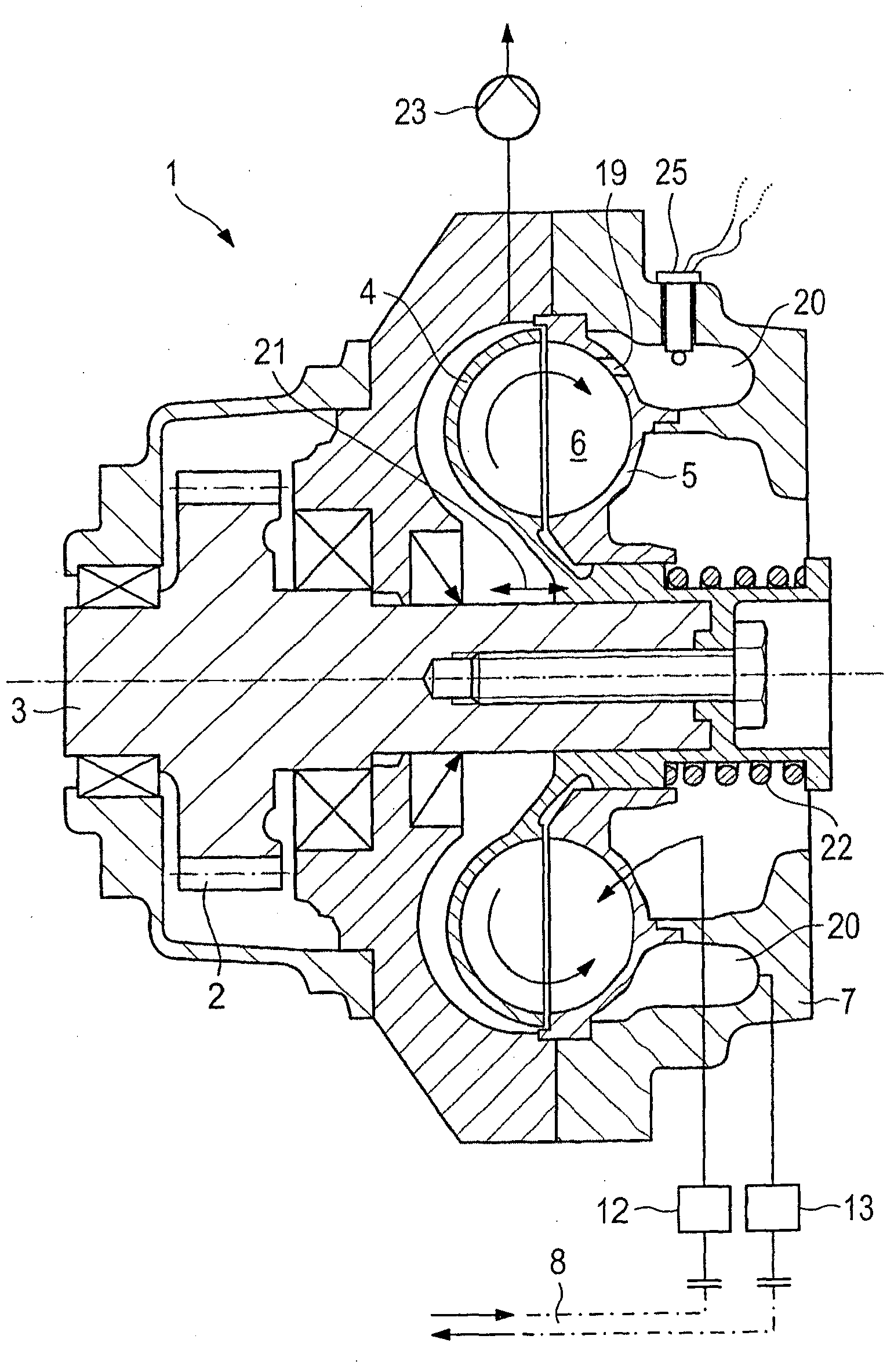
[0019] exist figure 1 The hydraulic retarder 1 can be identified in the description of . For example, it should be designed as a water retarder and be operated with cooling water of the drive train in commercial vehicles as the working medium. The hydrodynamic reducer 1 is driven by the pinion 2 and the shaft 3, the shaft and the pinion are designed as one piece or the pinion 2 is mounted on it accordingly. The pinion 2 can in this case mesh with a corresponding corresponding pinion, in particular on an auxiliary drive of the transmission or the like. The reducer 1 is therefore designed as a secondary water reducer. This structure is understood here purely as an example. The gear unit can be operated quite well with other operating media, such as oil or other suitable materials or material mixtures. This configuration can also be understood purely as a secondary reduction gear. The reduction gear can also be integrated in the transmission or be designed as an embedded red...


PUM


Abstract

A hydrodynamic retarder (1) comprises a working chamber (6), which is formed by a primary blade wheel (4) and a secondary blade wheel (5). Between the blade wheels, a circulating flow of a working medium develops during braking of the retarder. To this end, at least one valve device (12, 13) for controlling the inflowing and/or outflowing volumetric flow rate of the working medium is provided. A temperature sensor (25) is disposed on the side of the at least one valve device that faces the working chamber (6).

Description

technical field [0001] The invention relates to a hydrodynamic retarder of the type defined in detail in the preamble of claim 1 . Furthermore, the invention relates to a method for operating a hydrodynamic retarder, which has the features stated in the preamble of claim 7 . Background technique [0002] Hydrodynamic retarders are generally known as wear-free permanent brakes which are used, for example, in motor vehicles, in particular commercial vehicles or rail vehicles. The hydrodynamic retarder here comprises a working chamber formed by a primary impeller and a secondary impeller. The two impellers rotate relatively in the working chamber. When the reducer is in braking operation, the liquid working medium is located in the working chamber, and the working medium forms a circulating flow between the primary impeller and the secondary impeller. The primary impeller is usually designed to be rotatable. In this construction, the secondary impeller is typically fixedly c...

Claims


Application Information

Patent Timeline
IPC IPC(8): B60T1/087F16D57/04F16D66/00
CPCF16D2066/001F16D57/04B60T10/02F16D66/00B60T1/087
Inventor 托马斯·盖尔迪特尔·劳克曼托马斯·奥赫
Owner VOITH PATENT GMBH
Why Eureka
Try Eureka