Forming method of special-shaped pipe end and special-shaped clamping mold used

A molding method and mold clamping technology, which is applied in the direction of manufacturing tools, feeding devices, positioning devices, etc., can solve problems such as high requirements on the length of straight line sections, failure to meet precision requirements, and damage to pipe ends, so as to improve the processing range and design and manufacture The effect of low cost and high pass rate

Active Publication Date: 2015-08-12
GREE ELECTRIC APPLIANCES INC
View PDF7 Cites 0 Cited by
  • Summary
  • Abstract
  • Description
  • Claims
  • Application Information

AI Technical Summary

Problems solved by technology

However, since the pipe end is first formed and then bent, the length of the straight line is required to be greater than 90mm, and the pipe end is easily damaged during bending, which cannot meet the accuracy requirements and the pass rate is low

Method used


Image

  • Forming method of special-shaped pipe end and special-shaped clamping mold used
  • Forming method of special-shaped pipe end and special-shaped clamping mold used
  • Forming method of special-shaped pipe end and special-shaped clamping mold used

Examples


Embodiment Construction

[0029] Embodiments of the present invention are described in detail below in conjunction with accompanying drawings:

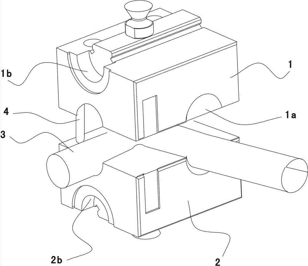
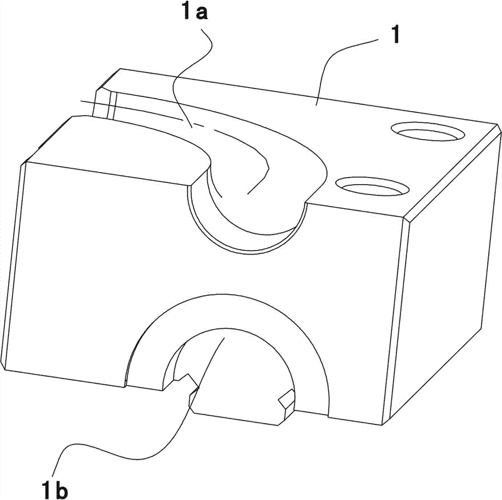
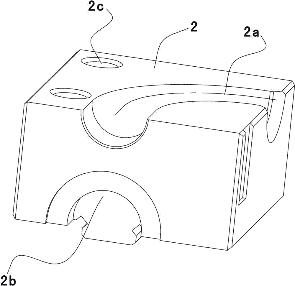
[0030] One of the embodiments of the special-shaped clamping mold of the present invention is as Figures 1 to 3 As shown, the special-shaped clamping mold is mainly composed of an upper clamping mold 1, a lower clamping mold 2 and a positioning device. An upper pipeline cavity 1a is provided on the working surface of the upper clamping mold 1, and an upper pipeline cavity 1a is arranged on the working surface of the lower clamping mold 2. There is a lower pipeline cavity 2a opposite to the upper pipeline cavity 1a. When the lower clamping mold 2 and the lower clamping mold 2 are closed, the upper pipeline cavity 1a and the lower pipeline cavity 2a are docked to form a 90-degree bend The pipeline cavity 6.

[0031] see Figure 4 , the pipeline cavity 6 is composed of a first straight section 61, a second straight section 63 and an arc section 62 with a smoot...


PUM

PropertyMeasurementUnit
diameteraaaaaaaaaa

Abstract

The invention discloses a special pipe end forming method. The special pipe end forming method orderly comprises the steps of: (1) bending a to-be-processed end of a pipeline piece into a required shape; (2) putting the bent end into a special clamping mould with a pipeline chamber to be clamped; and (3) carrying out the pipe end forming processing on the end with the pipe end forming method. According to the pipe end forming method disclosed by the invention, the end part of the pipeline piece is firstly bent, is then clamped by the special clamping mould, and is finally formed by a pipe end forming machine. The pipe end forming method has the advantages of high percent of pass, and high efficiency. Meanwhile, the invention further discloses the special clamping mould used by the pipe end forming method. The special clamping mould can realize the pipe end forming of the special pipeline pieces with angles, and has the requirement on the length of an expanding section of the pipeline that the length is larger than 50mm as compared with the existing pipe end forming requirement that the length of a linear section is larger than 90mm, so that the pipeline piece processing scope is greatly enhanced. In addition, the special clamping mould also has the advantages of low design and manufacture cost and easiness in operation.

Description

technical field [0001] The invention relates to the processing of metal pipes, in particular to a molding method of special-shaped pipe ends and the used special-shaped clamping mold. Background technique [0002] Pipe end forming refers to the use of forming machines to perform forming processes such as flaring, shrinking, positioning points, positioning rings, and flared mouths on the ends of pipe fittings. The molding method is as follows: first clamp the pipe end to be processed with the clamping mold on the molding machine, and then use the expansion and contraction mold to expand the pipe end, shrink the mouth, punch the positioning point, locate the ring, expand the bell mouth and other molding processes. Since the existing clamping molds are only suitable for forming the pipe ends of straight pipe fittings, and the length of the clamped straight line must be greater than 70 mm, the processing range is small, which cannot meet the requirements for pipe end molding of ...

Claims


Application Information

Patent Timeline
Patent Type & Authority Patents(China)
IPC IPC(8): B21D41/00B21D43/00
Inventor 陈怀礼
Owner GREE ELECTRIC APPLIANCES INC
Why Eureka
Try Eureka