
Zoom lens

A zoom lens and lens technology, applied in the field of wide-angle zoom lenses, can solve the problems of being unsuitable for imaging devices, high manufacturing costs, and large first lens groups, achieving excellent imaging performance, realizing manufacturing costs, and suppressing aberration changes Effect

Active Publication Date: 2013-03-06
TAMRON
View PDF5 Cites 11 Cited by
  • Summary
  • Abstract
  • Description
  • Claims
  • Application Information

AI Technical Summary

Problems solved by technology

These zoom lenses have an angle of view of about 100° at the wide-angle end, and can achieve a sufficient wide-angle. However, the first lens group is large, and it is not suitable for the recent strong desire for miniaturization of imaging devices.
In addition, since the glass lens disposed on the object side is formed with an aspheric surface, there is also a problem that the manufacturing cost is very high.

Method used


Image

  • Zoom lens
  • Zoom lens
  • Zoom lens

Examples


Embodiment 1

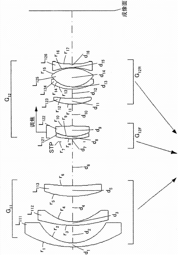
[0113] image 3 It is a sectional view along the optical axis showing the configuration of the zoom lens of the first embodiment. In this zoom lens, the first lens group G having negative refractive power is arranged in order from the object side not shown in the figure. 11 , the second lens group G with positive power 12 And constitute.

[0114] The first lens group G 11 , arrange the negative lens L sequentially from the object side 111 (first lens), negative lens L 112 (second lens), positive lens L 113 And constitute. Negative lens L 111 It consists of a meniscus spherical lens with the concave surface facing the image side. Negative lens L 112 Consists of an aspherical lens with a concave surface facing the image side. Also, in the negative lens L 112 The two sides form an aspheric surface.

[0115] Second lens group G 12 , the front group G with positive refractive power is arranged sequentially from the object side 12F , the rear group G with positive opti...

Embodiment 2

[0206] Figure 5 It is a cross-sectional view along the optical axis showing the configuration of the zoom lens of Example 2. In this zoom lens, the first lens group G having negative refractive power is arranged in order from the object side not shown in the figure. 21 , the second lens group G with positive power 22 And constitute.

[0207] The first lens group G 21 , arrange the negative lens L sequentially from the object side 211 (first lens), negative lens L 212 (second lens), positive lens L 213 And constitute. Negative lens L 211 It consists of a meniscus spherical lens with the concave surface facing the image side. Negative lens L 212 Consists of an aspherical lens with a concave surface facing the image side. Also, in the negative lens L 212 The two sides form an aspheric surface.

[0208] Second lens group G 22 , the front group G with positive refractive power is arranged sequentially from the object side 22F , the middle group G with positive optica...

Embodiment 3

[0298] Figure 7 It is a sectional view along the optical axis showing the configuration of the zoom lens of Example 3. In this zoom lens, the first lens group G having negative refractive power is arranged in order from the object side not shown in the figure. 31 , the second lens group G with positive power 32 And constitute.

[0299] The first lens group G 31 , arrange the negative lens L sequentially from the object side 311 (first lens), negative lens L 312 (second lens), positive lens L 313 And constitute. Negative lens L 311 It consists of a meniscus spherical lens with the concave surface facing the image side. Negative lens L 312 Consists of an aspherical lens with a concave surface facing the image side. Also, in the negative lens L 312 The two sides form an aspheric surface.

[0300] Second lens group G 32 , the front group G with positive refractive power is arranged sequentially from the object side 32F , the middle group G with positive optical powe...


PUM


Abstract

The present invention provides a zoom lens, which has a field angle more than 100 DEG, and is excellent in image formation performance, low in cost and small in shape. The zoom lens includes sequentially from an object side, a first lens section G11 having a negative refractive power and a second lens section G12 having a positive refractive power. The first lens section G11 includes sequentially from the object side, a negative lens L111, a negative lens L112, and a positive lens L113. Both surface of the negative lens L112 are aspheric. The second lens section G12 includes sequentially from the object side, a front group G12F having a positive refractive power and a rear group G12R having a positive refractive power. Both surfaces of a negative lens L126 included in the rear group G12R are aspheric. The zoom lens can maintain high imaging performance while achieving size reductions and wide angle views by satisfying given conditions.

Description

technical field [0001] The present invention relates to a compact wide-angle zoom lens. Background technique [0002] As a wide-angle zoom lens widely used in single-lens reflex cameras, there are four-group zoom lenses in which lens groups having negative, positive, negative, and positive refractive powers are sequentially arranged from the object side (see, for example, Patent Documents 1 to 3). .). [0003] The zoom lenses described in Patent Documents 1 to 3 all have lens groups having negative, positive, negative, and positive refractive powers arranged sequentially from the object side, and can achieve a magnification change of 1.5 times or more. The zoom lens described in Patent Document 1 can ensure a field of view of about 80° at the wide-angle end, and achieve a zoom of about 2.8 times. The zoom lens described in Patent Document 2 can ensure a field angle of about 105.8° at the wide-angle end, and realize a zoom of about 1.95 to 2.36 times. The zoom lens describ...

Claims


Application Information

Patent Timeline
Patent Type & Authority Applications(China)
IPC IPC(8): G02B15/177
CPCG02B15/14G02B27/646G02B15/177G02B27/64G02B15/1425
Inventor 李大勇
Owner TAMRON
Learn More