Driving circuit of triode and driving method thereof

A driving circuit and triode technology, which is applied in the direction of electrical components, output power conversion devices, etc., can solve the problem of high cost of driving circuits, and achieve the effect of reducing costs and avoiding deep saturation.

Active Publication Date: 2013-03-06
BYD SEMICON CO LTD
View PDF4 Cites 22 Cited by
  • Summary
  • Abstract
  • Description
  • Claims
  • Application Information

AI Technical Summary

Problems solved by technology

[0005] The purpose of the invention is to solve the problem of high cost in the drive circuit in the prior art

Method used


Image

  • Driving circuit of triode and driving method thereof
  • Driving circuit of triode and driving method thereof
  • Driving circuit of triode and driving method thereof

Examples


Embodiment 1

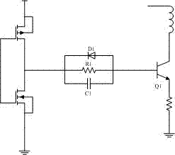
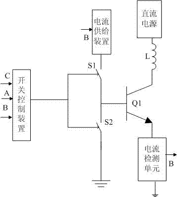
[0068] image 3 It is a drive circuit diagram, as can be seen from the figure, as can be seen from the figure, the drive circuit includes a current supply device, a switch control device, a first switch device and a second switch device, an inductance L, a DC power supply and a current detection unit; wherein , the current supply device is connected in series with the first switching device S1 and the second switching device S2 in sequence and grounded; the current supply device is connected to the base of the triode Q1 through the first switching device S1, and the emitter of the triode is grounded through the current detection unit, where the current The position of the detection unit is only one implementation mode. The position of the current detection unit can be changed, as long as it can detect the collector current of the triode. The current detection unit provides the detection voltage B for the switch control device and the current supply device. The collector of the ...

Embodiment 2

[0077] Figure 6 It is a diagram of the switching power supply module. It can be seen from the figure that the switching power supply includes a rectifier module, a power supply module, a feedback module, a control chip, a primary coil L, an output circuit, a current detection unit and a triode; the rectifier module rectifies the input AC power H Provide stable DC voltage or current for the power supply module, feedback module and primary coil L, the primary coil L is connected to the collector of the triode, the output circuit provides the output voltage for the outside, and the feedback module provides the control chip with the increase and decrease of the output voltage With the reduced feedback voltage, the power supply module supplies power to the control chip, and the current detection unit collects the collector current of the triode to provide a detection voltage for the control chip. The current that increases when the collector current of a transistor increases or de...


PUM


Abstract

The invention relates to a driving circuit of a triode. The circuit comprises a current supply device, a first switch device, a second switch device, a switch control device, an inductor, a direct-current power supply and a current detection unit, wherein the current supply device is grounded after being sequentially connected with the first switch device and the second switch device; the triode is connected between the first switch device and the second switch device, the direct-current power supply is connected with the collecting electrode of the triode, and an emitting electrode of the triode is grounded; the switch control device receives a detection voltage provided by the current detection unit and an externally supplied control voltage to control the on-off states of the first switch device and the second switch device so as to control the on-off state of the triode; and the current supply device supplies a direct current which reflects the changing of the current of the collecting electrode to the base electrode of the triode. By utilizing the driving circuit of the triode, the turn-off time of the switch is shortened, and the power dissipation is reduced; and meanwhile, the invention discloses a driving method of the driving circuit of the triode and a switch power supply.

Description

technical field [0001] The invention relates to a driving circuit, in particular to a triode driving circuit and a driving method thereof. Background technique [0002] Power converters are currently widely used in portable devices such as mobile phones, digital cameras, MP3, etc. Because it uses a low-voltage mains supply, powering it or charging its batteries requires converting the power from the 220V AC of traditional household power to low-voltage DC. [0003] Power converters can be broadly classified into linear converters and switching converters. Compared with linear converters, switching converters currently occupy an absolute dominant position due to their advantages of high efficiency, small size, and light weight. As one of the cores of switching converters, switching tubes usually use power transistors. Power transistors can be broadly classified into field effect transistors, bipolar transistors, and insulated gate transistors. In the field of low-powe...

Claims


Application Information

Patent Timeline
Patent Type & Authority Applications(China)
IPC IPC(8): H02M1/08
Inventor 叶文辉杨小华
Owner BYD SEMICON CO LTD
Why Eureka
Try Eureka