
Dump truck

A dump truck and cooling oil technology, which is applied to vehicle parts, brakes, gear lubrication/cooling, etc., can solve problems such as increased horsepower consumption, and achieve the effects of preventing leakage and suppressing internal pressure rise

Active Publication Date: 2013-03-06
KOMATSU LTD
View PDF8 Cites 2 Cited by
  • Summary
  • Abstract
  • Description
  • Claims
  • Application Information

AI Technical Summary

Problems solved by technology

[0006] However, in Patent Document 1, during normal running without using the speed reducer, the cooling oil is usually discharged from the hydraulic pump at the same flow rate as when the speed reducer is used. The horsepower consumption of the pump increases, and there is a certain limit in reducing fuel consumption.

Method used


Image

  • Dump truck
  • Dump truck
  • Dump truck

Examples

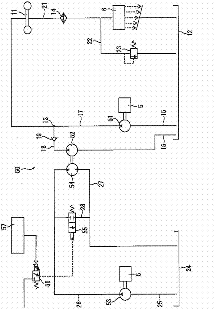

Embodiment Construction

[0025] Hereinafter, one embodiment of the present invention will be described based on the drawings.

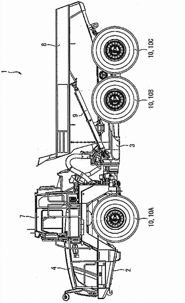
[0026] figure 1 , figure 2 Among them, the dump truck 1 is configured as an articulated dump truck in which a front frame 2 and a rear frame 3 are flexibly connected.

[0027] An engine 5 ( figure 2 ). The rear part of the front frame 2 is equipped with a transmission 6 ( figure 2 ), above which a cab 7 is arranged.

[0028] A vehicle body 8 is mounted on the rear frame 3 , and the vehicle body 8 heaves relative to the rear frame 3 by a pair of left and right hydraulic actuators 9 .

[0029] In addition, a pair of left and right front wheels 10 (10A) are provided on the front frame 2, and a pair of left and right rear front wheels 10 (10B) and rear rear wheels 10 (10C) are provided on the rear frame 3, and the entirety of the six wheels is driven. . The cooling system 50 of the present embodiment is applied to the center brake 11 as a brake device for the rear front...


PUM


Abstract

A dump truck includes: an oil-cooling center brake (11); a first hydraulic pump (51) supplying cooling oil to the center brake (11); a second hydraulic pump (52) supplying cooling oil to the center brake (11) in addition to the cooling oil from the first hydraulic pump (51); a hydraulic motor (54) driving the second hydraulic pump (52); a third hydraulic pump (53) supplying hydraulic oil to the hydraulic motor (54); an open / close valve (55) letting the hydraulic oil bypass the hydraulic motor (54); and a controller (57) controlling a bypass flow amount at the open / close valve (55). A capacity of the first hydraulic pump (51) corresponds to a flow amount of the cooling oil required to lubricate a transmission (6). A capacity of the second hydraulic pump (52) corresponds to a flow amount for compensating the cooling oil from the first hydraulic pump (51) when a brake is off. A capacity of the third hydraulic pump is smaller than the capacity of the second hydraulic pump (52).

Description

technical field [0001] The present invention relates to a dump truck, and more particularly to a dump truck configured such that a brake device is also cooled by cooling oil supplied to a transmission. Background technique [0002] Conventionally, in dump trucks, a brake device for a service brake that applies brakes by operating a brake pedal may be used as it is as a speed reducer when going downhill or the like. That is, by turning on the speed reducer lever and the speed reducer switch, the brake device operates as a speed reducer to apply the brakes. [0003] As such a brake device, when a wet multi-plate brake is used, it is necessary to supply cooling oil in order to absorb heat generated during braking. The cooling oil is lubricating oil for the transmission that transmits the power of the engine to the wheels, and is supplied from the transmission oil pan via a hydraulic pump driven by the engine. [0004] At this time, the amount of cooling oil supplied differs g...

Claims


Application Information

Patent Timeline
IPC IPC(8): F16H57/04B60T5/00F16D65/78
CPCF16D65/78B60T5/00B60T10/04
Inventor 不动寺隆资
Owner KOMATSU LTD
Learn More