Power tool and battery pack for use in the power tool
A technology for electric tools and battery packs, which is applied to battery pack parts, non-aqueous electrolyte storage batteries, batteries, etc., and can solve problems such as reduced cycle life
- Summary
- Abstract
- Description
- Claims
- Application Information
AI Technical Summary
Problems solved by technology
Method used
Image
Examples
no. 1 example
[0121] Hereinafter, embodiments of the present invention will be described with reference to the accompanying drawings. In the following description, a vertical direction, a horizontal direction, and a front-rear direction represent directions shown in the drawings referred to.
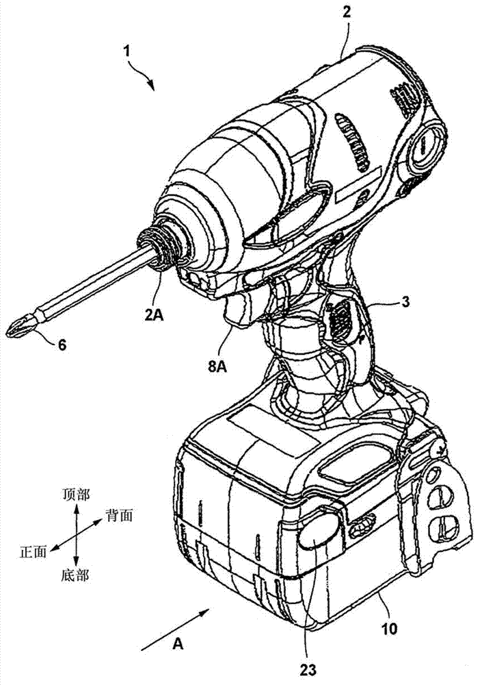
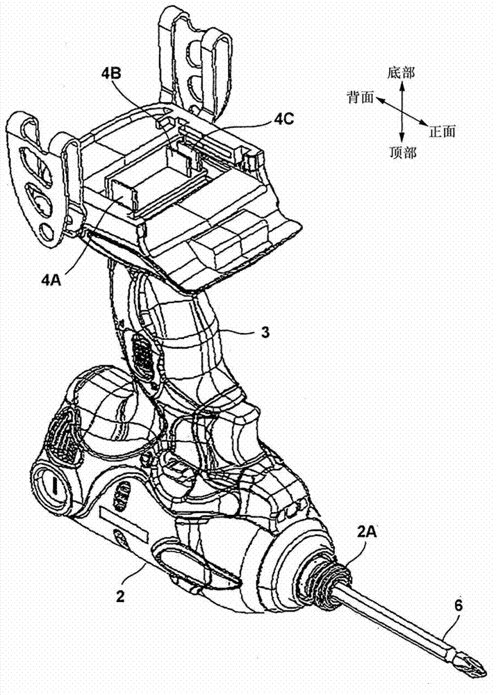
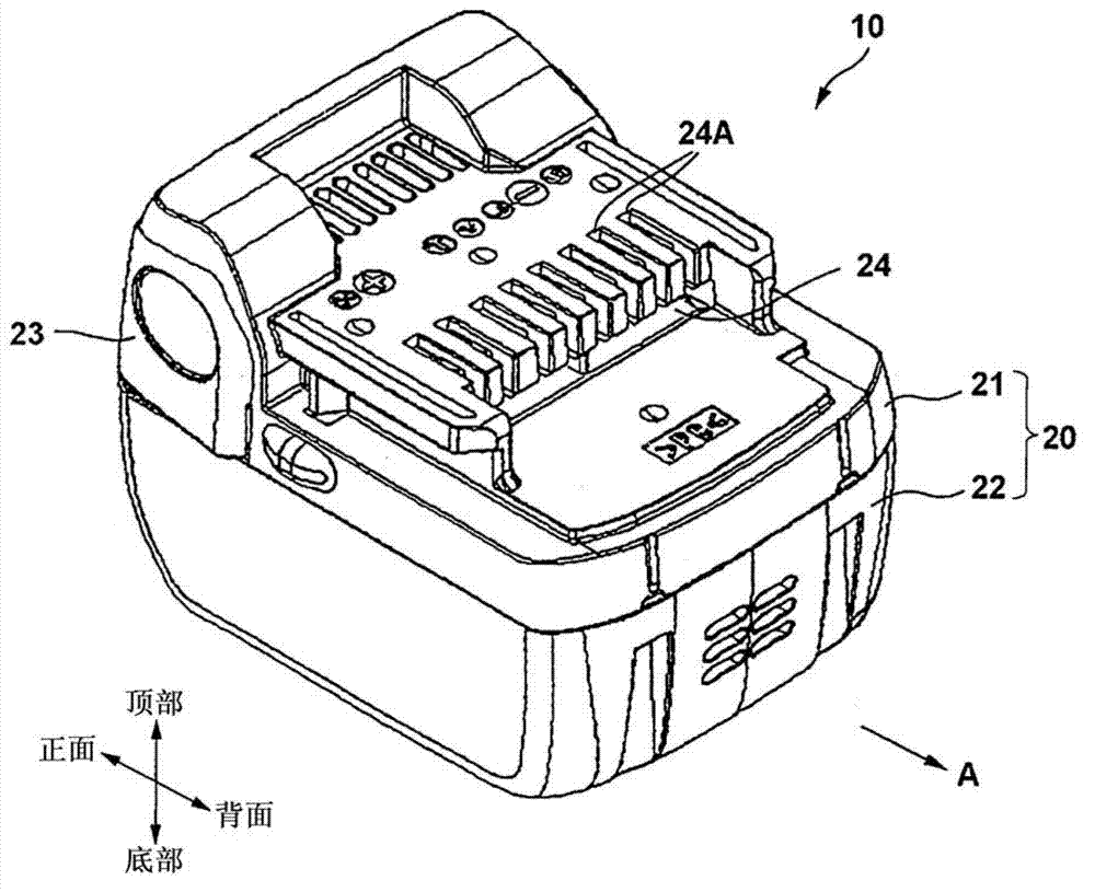
[0122] figure 1 An example of an electric tool mounted with a battery pack according to the present invention is shown. figure 1 An example of using a cordless drill as the electric tool 1 is shown. The electric tool 1 includes a main body portion 2 as a device main body, and a battery pack 10 detachably attached to the main body portion 2 . The battery pack 10 is detachably attached to one end (lower end) of the handle portion 3 in an extending direction along the front-rear direction of the main body portion 2 . The operation portion 23 is arranged on the battery pack 10 , and the operation portion 23 functions as a locking mechanism when the battery pack is installed and also functions as a re...
no. 2 example
[0164] Subsequently, will refer to Figure 10 and Figure 11 An overcurrent protection circuit according to a second embodiment of the present invention is described. Similar to the first embodiment, in the second embodiment, the overcurrent state is detected in the battery pack 10 by using the microcomputer 60 mounted on the board 40 of the battery pack 10 . However, the program executed by the microcomputer 60 is different from that in the first embodiment, and compared with that in the first embodiment, advanced overcurrent protection is performed.
[0165] Figure 10 is a current waveform diagram during operation of the overcurrent protection circuit according to the second embodiment. The horizontal axis is the elapsed time period (seconds), and the vertical axis is the discharge current value (unit A) from the battery pack 10 . The discharge current value is represented by discharge curve 450 . Figure 10 A discharge curve 450 showing a discharge is divided into six...
no. 3 example
[0185] Subsequently, will refer to Figure 12 and Figure 13 An overcurrent protection circuit according to a third embodiment of the present invention is described. In the first embodiment, the microcomputer 60 is mounted on the board 40 of the battery pack 10 , and an overcurrent state within the battery pack 10 is detected using the microcomputer 60 . The third embodiment is the same as the first embodiment in that an overcurrent protection circuit is mounted on the board 240 of the battery pack 210, but is realized by using a dedicated battery protection IC 253 instead of using a circuit of a microcomputer. Furthermore, a FET for interrupting overcurrent is arranged not in the battery pack 210 but on the electric tool 101 side, and the FET can be controlled from the outside while the on and off operations of the FET are controlled from the battery pack 210 side. The same components as those in the second embodiment are denoted by the same reference numerals.
[0186] ...
PUM
 Abstract
Description
Claims
Application Information
 - R&D
- Intellectual Property
- Life Sciences
- Materials
- Tech Scout
- Unparalleled Data Quality
- Higher Quality Content
- 60% Fewer Hallucinations
Browse by: Latest US Patents, China's latest patents, Technical Efficacy Thesaurus, Application Domain, Technology Topic, Popular Technical Reports.
© 2025 PatSnap. All rights reserved.Legal|Privacy policy|Modern Slavery Act Transparency Statement|Sitemap|About US| Contact US: help@patsnap.com


