Pulmonary valve stent with anchoring mechanism

A pulmonary artery and valve technology, applied in the field of medical devices, can solve problems such as limited effectiveness, and achieve the effects of improving stability, reducing friction, and good elasticity

Active Publication Date: 2015-08-12
NINGBO JENSCARE BIOTECHNOLOGY CO LTD
View PDF9 Cites 0 Cited by
  • Summary
  • Abstract
  • Description
  • Claims
  • Application Information

AI Technical Summary

Problems solved by technology

[0009] To sum up, a considerable part of the research focuses on how to avoid the displacement of the pulmonary valve stent and solve the problem of regurgitation. Many researchers have also proposed some solutions, but the effect is limited.

Method used


Image

  • Pulmonary valve stent with anchoring mechanism
  • Pulmonary valve stent with anchoring mechanism
  • Pulmonary valve stent with anchoring mechanism

Examples


specific Embodiment 1

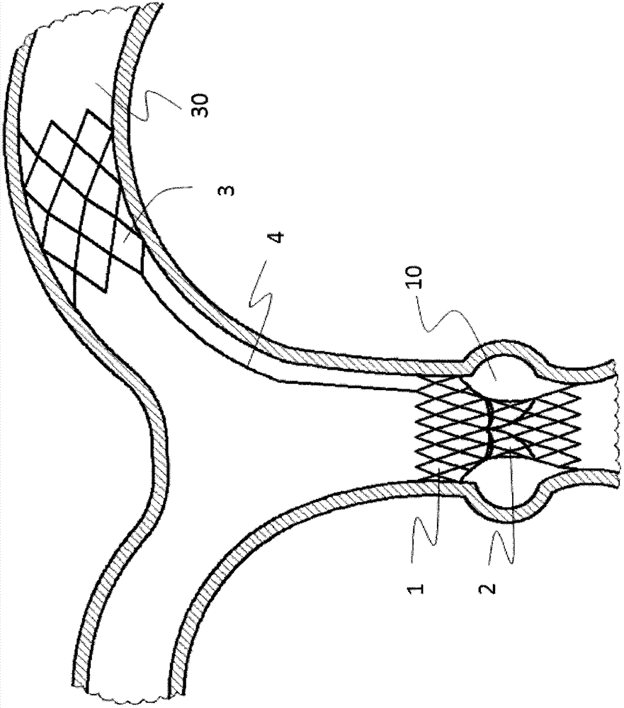
[0051] Such as figure 1 As shown, a pulmonary valve stent with an anchoring mechanism includes a valve sewing section 1 and an artificial valve 2, the artificial valve 2 is connected to the valve sewing section 1, and the valve sewing section 1 is located on the right ventricular outflow tract or the main pulmonary artery 10 when it is released, and the pulmonary valve stent also includes an anchoring mechanism 3, and the proximal end of the anchoring mechanism 3 is connected to the valve sewing section through a transition connecting rod 4 1, the anchoring mechanism 3 is located in the pulmonary artery branch vessel 30 after release. There are two reasons why the anchoring mechanism 3 is placed in the pulmonary artery branch vessel 30. The first is that patients with the second stage of tetralogy of Fallot are usually accompanied by dilation of the main pulmonary artery 10, and the expanded blood vessel loses its original elasticity. Thereby its frictional force to valve ste...

specific Embodiment 2

[0055] Such as Figure 6 As shown, a pulmonary valve stent with an anchoring mechanism includes a valve sewing section 1 and an artificial valve 2, the artificial valve 2 is connected to the valve sewing section 1, and the valve sewing section 1 is located on the right ventricular outflow tract or the main pulmonary artery 10 when it is released, and the pulmonary valve stent also includes an anchoring mechanism 3, and the proximal end of the anchoring mechanism 3 is connected to the valve sewing section through a transition connecting rod 4 1, the anchoring mechanism 3 is located in the pulmonary artery branch vessel 30 after release.

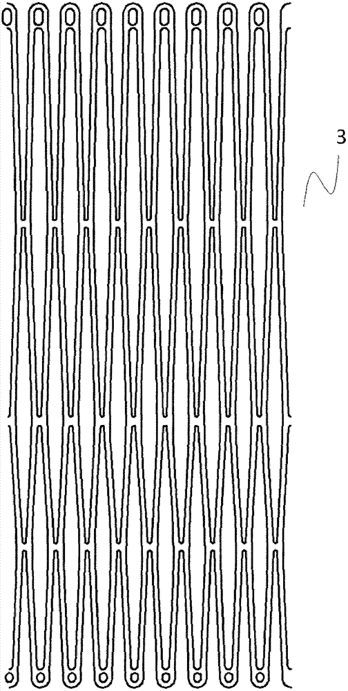
[0056] Such as Figure 7a As shown, the anchoring mechanism 3 is a braided stent made of shape memory material or elastic material, preferably nickel-titanium shape memory alloy.

[0057] Such as Figure 7b and 7c As shown, the outer surface of the anchoring mechanism 3 is fully or partially covered with a film 31 . The material of the me...

specific Embodiment 3

[0067] The difference between this embodiment and the specific embodiment 2 is that the anchoring mechanism 3, the transition connecting rod 4 and the valve sewing section 1 are integrally carved with a shape memory material tube, more preferably nickel-titanium shape memory Made of alloy tube integrally carved, such as Figure 11 shown.


PUM


Abstract

The invention relates to a pulmonary valve stent with an anchor mechanism, which comprises a valve suture section (1) and an artificial valve (2), wherein the artificial valve (2) is connected with the valve suture section (1), and the valve suture section (1) is positioned at a right ventricular outflow tract or a main pulmonary artery (10) after being released. The pulmonary valve stent further comprises the anchor mechanism (3), wherein the near end of the anchor mechanism (3) is connected with the far end of the valve suture section (1) by a transition connecting rod (4), and the anchor mechanism (3) is positioned in a pulmonary artery branching vessel (30) after being released. According to the pulmonary valve stent, as the anchor mechanism is placed in the pulmonary artery branching vessel and connected with the valve suture section positioned at the right ventricular outflow tract or the main pulmonary artery by the transition connecting rod, the stability of the valve stent can be improved significantly, and displacement of the pulmonary valve stent is avoided.

Description

Technical field: [0001] The invention belongs to the field of medical equipment, and in particular relates to a pulmonary valve stent with an anchoring mechanism. Background technique: [0002] Congenital heart disease is a cardiovascular malformation caused by abnormal development of heart vessels during fetal period, and it is the most common heart disease in children. Its incidence rate accounts for about 0.8% of births, and 60% of them die within 1 year of age. It is estimated that 150,000 babies are born with various congenital heart diseases every year in my country, and about 30% of them may die in infancy. Tetralogy of Fallot is the most common cyanotic congenital heart disease in surviving infants, accounting for 10%-15% of all congenital heart diseases. That is, at least 10,000 patients with tetralogy of Fallot survive to the age of 20 every year. [0003] Typical tetralogy of Fallot includes pulmonary stenosis, aortic overriding, ventricular septal defect, and ...

Claims


Application Information

Patent Timeline
Patent Type & Authority Patents(China)
IPC IPC(8): A61F2/24
Inventor 李毅斌徐志云孙建国张鹏云信朝华
Owner NINGBO JENSCARE BIOTECHNOLOGY CO LTD
Why Eureka
Try Eureka