High-frequency vibration auxiliary foil plate micro-blanking forming method

A high-frequency vibration and micro-blanking technology, which is applied in the direction of using vibrating fluids and pushing out equipment, can solve the problems of increased punching power due to size effects, small gap between punch and die, and low service life, so as to inhibit crack growth and punching. The effect of small force and reduced ratio

Active Publication Date: 2014-12-10
HARBIN INST OF TECH
View PDF5 Cites 0 Cited by
  • Summary
  • Abstract
  • Description
  • Claims
  • Application Information

AI Technical Summary

Problems solved by technology

[0003] In order to solve the problems of the existing high-precision foil plate blanking forming, the gap between the convex and concave dies is small, the size effect significantly increases the punching power, the mold wears seriously, and the service life is low, and then proposes high-frequency vibration assisted foil plate micro-punching forming method

Method used


Image

  • High-frequency vibration auxiliary foil plate micro-blanking forming method

Examples


specific Embodiment approach 1

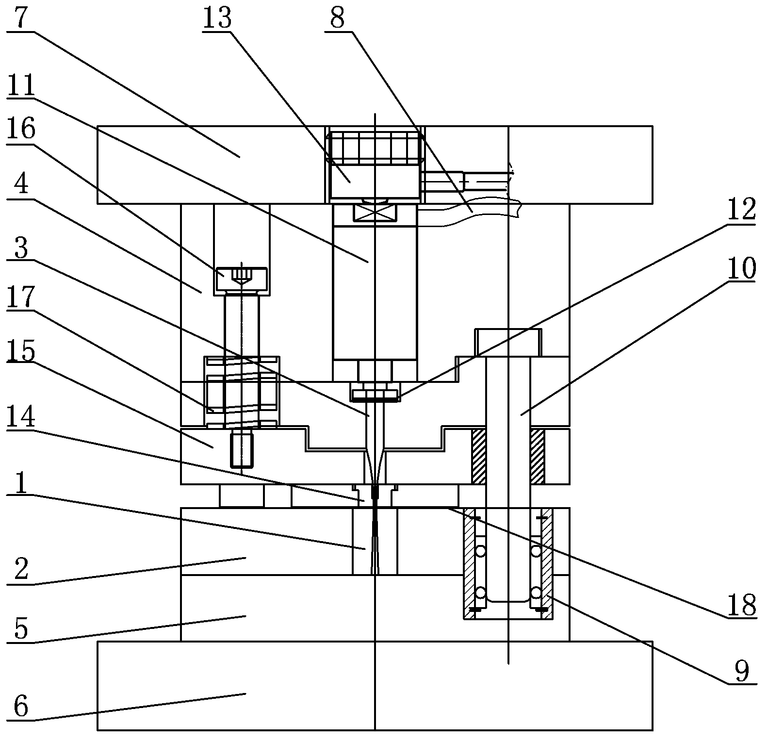
[0012] Specific implementation mode one: combine figure 1 Describe this embodiment, the high-frequency vibration assisted foil plate micro-punching forming device in this embodiment includes a die 1, a die fixing plate 2, a punch 3, a punch fixing plate 4, a lower backing plate 5, and a lower template 6 , upper template 7, high-frequency power supply 8, guide sleeve 9, guide post 10 and vibration assembly, die fixing plate 2, lower backing plate 5, and lower template 6 are connected sequentially from top to bottom, upper template 7, punch fixing plate 4. Arranged sequentially above the die fixing plate 2 from top to bottom, the die 1 is embedded in the middle of the upper surface of the die fixing plate 2, and the vibrating assembly and punch 3 are sequentially inserted on the punch fixing plate from top to bottom 4, and the center line of the punch 3 coincides with the center line of the die 1, the vibration assembly is connected with the high-frequency power supply 8, the gu...

specific Embodiment approach 2

[0013] Specific implementation mode two: combination figure 1 Describe this embodiment, the vibration assembly of the high-frequency vibration auxiliary foil plate micro-punching forming device in this embodiment includes a piezoelectric ceramic 11 and a disc spring 12, and the upper end of the punch 3 passes through the disc spring 12 and the piezoelectric ceramic 11. the lower end connection.

[0014] In this embodiment, the punch 3 is constantly vibrating at high frequency under the action of the piezoelectric ceramic 11 . Due to the high-frequency vibration of the punch 3 , the deformation resistance of the foil plate 18 is reduced, so the deformation is relatively easy.

[0015] Other components and connections are the same as those in the first embodiment.

specific Embodiment approach 3

[0016] Specific implementation mode three: combination figure 1 To describe this embodiment, the high-frequency vibration assisted foil plate micro-punching forming device in this embodiment further includes a pressure sensor 13 , and the upper end of the piezoelectric ceramic 11 is connected to the pressure sensor 13 . In this embodiment, the pressure sensor 13 is connected with the data acquisition device, and the data acquisition device can collect data, which is convenient for data analysis on the punching and forming process. Other compositions and connections are the same as those in Embodiment 1 or 2.


PUM


Abstract

The invention relates to a micro-blanking forming device and a forming method, in particular to a high-frequency auxiliary micro-blanking forming device and a method for a foil plate. The device and the method aim at solving the problems in the existing high-precision blanking forming of the foil plate that an interval between a female die and a male die is small, a blanking force is significantly increased by a size effect, and the dies are badly worn and have short service lives. The device comprises a female die fixing plate, a lower bolster and a lower die plate that are sequentially connected from the top down, wherein an upper die plate and a male die fixing plate are sequentially arranged above the female die fixing plate; a female die is embedded into the middle part of the upper surface of the female die fixing plate; a vibration component and a punch are sequentially mounted in the male die fixing plate from the top down in an inserting manner; a middle line of the punch is coincided with that of the female die; the vibration component is connected with a high-frequency power source; a guide sleeve is mounted on the upper surface of the female die fixing plate in an inserting manner; the upper end of a guide column is mounted in the male die fixing plate in an inserting manner; and the lower end of the guide column is mounted in the guide sleeve in an inserting manner. The device and the method are used for blanking forming of the foil plate.

Description

technical field [0001] The invention relates to a micro-punching forming method, in particular to a micro-punching forming method of a foil plate assisted by high-frequency vibration. Background technique [0002] With the development of microsystem technology and microelectronics technology, the demand for micro-components of foil plate is increasing day by day, but the expansion of application scope also puts forward higher requirements for the forming quality of micro-components of foil plate. For example, micro-components of foil plate not only need It has high geometric dimension accuracy, and also requires good punching section quality, high shape and position accuracy, etc. Due to the small thickness of these foil plate micro-components, generally less than 0.2mm, and the overall size of the component is less than 1.0mm, it is difficult to perform secondary processing, and it is necessary to punch out a micro-foil that meets the requirements of dimensional accuracy an...

Claims


Application Information

Patent Timeline
Patent Type & Authority Patents(China)
IPC IPC(8): B21D33/00B21D45/02B06B1/06
Inventor 王春举单德彬郭斌徐杰皇韶峰
Owner HARBIN INST OF TECH
Why Eureka
Try Eureka