

Bolted steel angle-based steel bridge out-of-plane distortion fatigue reinforcement structure
A steel bridge deck and angle steel technology, applied in bridge reinforcement, bridges, bridge parts, etc., can solve the problems of weakening the rigidity of the original structure, and achieve the effects of preventing accidental falls, simple operation, and inhibiting initiation and expansion
- Summary
- Abstract
- Description
- Claims
- Application Information
AI Technical Summary
Problems solved by technology
Method used
Image

Examples
Embodiment 1
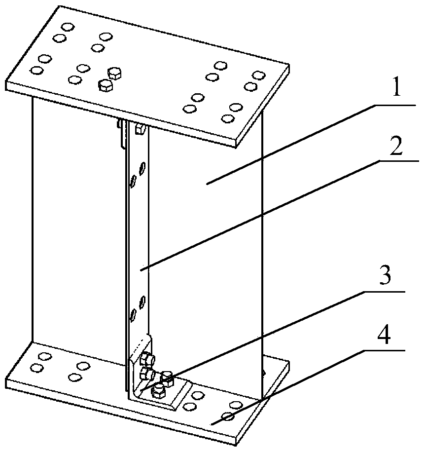
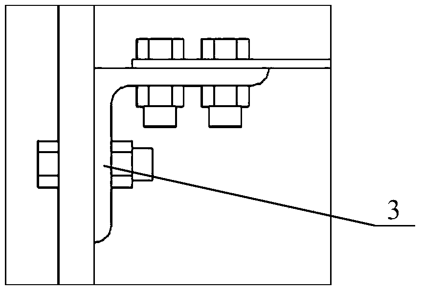
[0017] The reinforced test piece selected in this embodiment is an I-shaped steel beam welded by the flange plate 4, the stiffener 2 and the web 1. The flange plate 4 is a rectangular steel plate with a length of 600 mm, a width of 300 mm, and a thickness of 24 mm; the web plate 1 is a rectangular steel plate with a length of 600 mm, a height of 870 mm, and a thickness of 8 mm; the stiffener 2 is a rectangular steel plate with a length of 120 mm and a height of 790 mm , a rectangular steel plate with a thickness of 6mm; between the flange plate 4 and the stiffener 2 at the web gap, use high-strength bolts to bolt and reinforce the angle steel 3, and leave a distance of 10mm between the side end of the angle steel and the web 1, see Figure 1~2 , The angle steel 3 of the present embodiment selects the equal-leg single angle steel, and the single angle steel selects the standard angle steel of L140mm×140mm×14mm.
[0018] Before the reinforcement, the preparatory work for the rei...
Embodiment 2
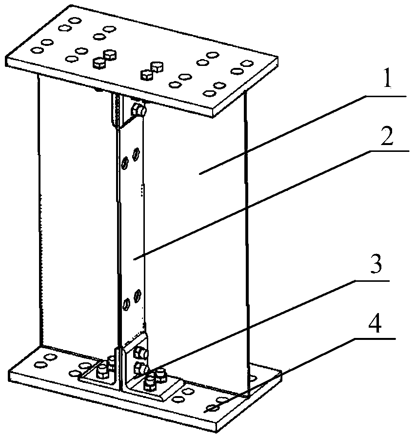
[0020] The single angle steel in the above-mentioned embodiment 1 is replaced by a double angle steel whose specification is L140mm * 140mm * 14mm, such as image 3 As shown, other components and their connections are the same as those in Embodiment 1.
[0021] The reinforcement method is the same as in Example 1.
Embodiment 3
[0023] The single angle steel in the above-mentioned embodiment 1 is replaced by a T-shaped angle steel with a specification of 280mm * 140mm * 14mm * 14mm, such as Figure 4 As shown, other components and their connections are the same as those in Embodiment 1.
[0024] The reinforcement method is the same as in Example 1.
PUM
| Property | Measurement | Unit |
|---|---|---|
| Length | aaaaa | aaaaa |
| Width | aaaaa | aaaaa |
| Thickness | aaaaa | aaaaa |
Abstract
Description
Claims
Application Information