Back-hydrofoil high-speed wing rowboat

A technology of wing skids and hydrofoils, which is applied in the directions of ships, hull bows, stern columns, etc., can solve the problems that limit the improvement of the overall arrangement performance and overall economic performance of the boat, strict weight distribution requirements, and high construction costs, so as to overcome the problems of propulsion devices. Effects of complex, lateral and vertical stability improvements

Inactive Publication Date: 2013-03-13
JIANGSU UNIV OF SCI & TECH
View PDF10 Cites 8 Cited by
  • Summary
  • Abstract
  • Description
  • Claims
  • Application Information

AI Technical Summary

Problems solved by technology

[0003] When the planing boat sails at high speed on the water surface, most or most of its weight is supported by hydrodynamic lift, and only a part or a small part of its weight is supported by water buoyancy. Strict weight distribution requirements, this shortcoming seriously limits the improvement of the general layout performance and overall economic performance of the boat, especially when sailing at high speed, the side splash of the sliding surface is serious, which has an adverse effect on the fast performance and sailing economic performance
When a hydrofoil boat sails at high speed on the water surface, it relies on the hydrodynamic lift generated by the hydrofoil to lift the hull completely or mostly out of the water, and the hydrodynamic lift of the hydrofoil supports most of the weight of the boat. The rapidity is more than 15% higher than that of the planing boat. It overcomes many shortcomings of the planing boat, but its stall in the waves is large, and the propulsion device and other turbine systems are more complicated and expensive.

Method used


Image

  • Back-hydrofoil high-speed wing rowboat
  • Back-hydrofoil high-speed wing rowboat
  • Back-hydrofoil high-speed wing rowboat

Examples


Embodiment Construction

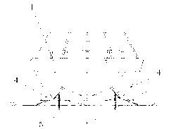
[0028] The present invention will be further described below in conjunction with drawings and embodiments.

[0029] Such as Figure 1 to Figure 9 As shown, the present invention includes a hull 1 and a power plant 2. The bottom of the rear end of the hull 1 is stepped up in a step-like manner, and the hull is longitudinally divided into a front hull 11 and a rear hull with the overall step-up position 3 as an interface. 12. The bottom line of the front hull 11 gradually transitions backward from the V-shaped A-A cross-section at the bow to the shallow V-shaped B-B cross-section in the midship area of ​​the front hull 11, and then gradually transitions from the shallow V-shaped B-B cross-section The line pattern to the bottom of the rear hull 12 is a horizontal or shallow inverted V-shaped or shallow inverted arc-shaped C-C cross-section, and the line pattern to the bottom of the stern of the rear hull 2 ​​is a horizontal or shallow V-shaped D-D cross-section. The front hull 1...


PUM


Abstract

The invention discloses a back-hydrofoil high-speed wing rowboat, which comprises a boat body and a motive power device, wherein the bottom of the back end of the boat body is in an integral step lifting in a step shape, the bottom linetype of a front boat body is backwards and gradually transited to the shallow V-shaped transverse cross section from the V-shaped transverse cross section of a boat bow part, and then, the bottom linetype of a back boat body is in a horizontal or shallow reverse V-shaped or shallow reverse circular arc-shaped transverse cross section until the bottom linetype of the bow part of the back boat body is in a horizontal or shallow V-shaped transverse cross section. A back hydrofoil is arranged under the bottom of the back boat body, and two pairs of sheet bodies with tapered wing-shaped transverse cross section in horizontal staggered and transverse symmetry in the longitudinal direction respectively and obliquely extend from two sides of the front boat body. The back-hydrofoil high-speed wing rowboat has the advantages that the splashing kinetic energy of the sliding surface fluid can be better absorbed, and the comprehensive performance of the rowboat is better than that of a planing boat and a gliding-hydrofoil boat. The rapidity of the rowboat is improved by more than 10 percent than that of the planing boat, meanwhile, the transverse and longitudinal stability of the rowboat is greatly improved than that of the planing boat and the ordinary gliding-hydrofoil, and in addition, good character that the planing boat can surf the beach is reserved.

Description

technical field [0001] The invention relates to a high-performance boat, in particular to a high-speed wing skid with superior overall performance to a planing boat and a wing skid and with hydrofoils placed behind. It belongs to the technical field of high-performance ships. Background technique [0002] The planing boat is the main member of the high-speed boat family, and it is also the boat type with the largest number of all kinds of speedboats. With the continuous upgrading of this type of boat, no matter in civil transportation, tourism and sightseeing, or on military speedboats, its The application prospect is very broad. [0003] When the planing boat sails at high speed on the water surface, most or most of its weight is supported by hydrodynamic lift, and only a part or a small part of its weight is supported by water buoyancy. Strict requirements on weight distribution seriously limit the improvement of the overall layout performance and overall economic perfor...

Claims


Application Information

Patent Timeline
IPC IPC(8): B63B3/46B63B3/40B63B1/28
Inventor 朱仁庆杨松林崔健陈鹏
Owner JIANGSU UNIV OF SCI & TECH
Why Eureka
Try Eureka