
Electroplating clamp

A technology of electroplating fixtures and chucks, applied in electrical components, electrolysis process, electrolysis components, etc., can solve the problems of electroplating liquid barrel damage, copper particles sticking in, bottom collision, etc., to prolong the service life and have strong corrosion resistance. , The effect of preventing corrosion

Inactive Publication Date: 2013-03-13
东莞市益泉电热挂具有限公司
View PDF3 Cites 10 Cited by
  • Summary
  • Abstract
  • Description
  • Claims
  • Application Information

AI Technical Summary

Problems solved by technology

[0002] The traditional electroplating fixture is composed of a main clamp and a secondary clamp. The main and secondary clamps are set between the head ends of the main clamp and the secondary clamp to clamp the circuit board and then carry out the electroplating process. Since the jaws of the plating fixture are Bare, affected by its bare state. During the electroplating process, the clips are easily damaged by copper coating and chemical solution. At the same time, copper particles will stick into the positioning holes of the circuit board, which will affect the performance of the circuit board and cause The waste of electroplating copper, even stained with the liquid will cause adverse chemical reactions and affect the performance of the circuit board
At the same time, since the main and auxiliary clamps form a single positioning point positioning structure for the circuit board, the circuit board will rotate relative to the clamping point during the processing, and because the fixed point (electrode conduction point) of the flat tight circuit board is not It must be the middle part. Its fixation is unstable and the height of the bottom of the circuit board is inconsistent. When sinking, the uniform level height cannot be accurately calculated, causing the bottom to collide with the electric liquid tank and be damaged.

Method used


Image

  • Electroplating clamp
  • Electroplating clamp
  • Electroplating clamp

Examples


Embodiment Construction

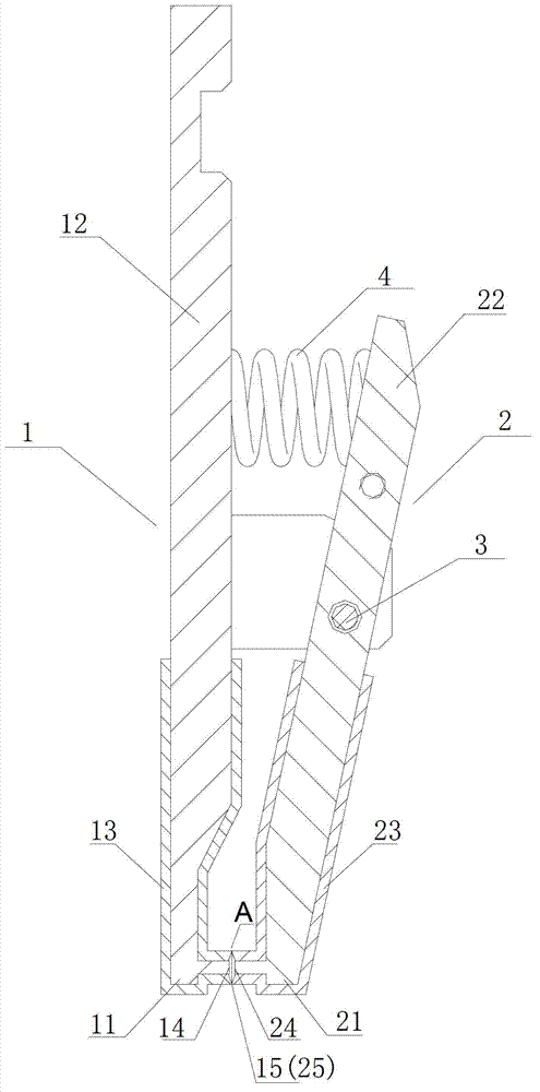
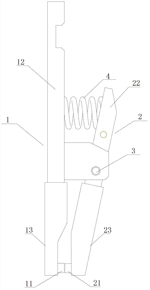
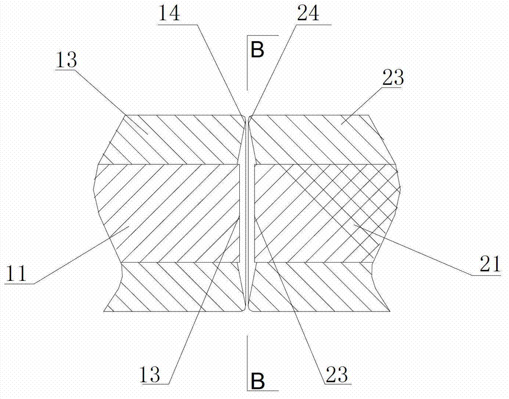
[0023] like figure 1 , figure 2 , image 3 and Figure 4 As shown, an electroplating fixture includes a main clamp 1 and a sub-clamp 2 integrated by a pin shaft 3, a main and sub-clamp head 11, 21 opposite to each other at the front end, and a main and sub-clamp handle 12, 22 opposite to each other at the rear end. , elastic element 4 is arranged between the main and auxiliary chuck handles 12, 22 to clamp the main and auxiliary chucks 11, 21. Electrode conduction contact surfaces 14 , 24 are formed therebetween, and insulating jackets 13 , 23 around the ring electrode conduction contact surfaces 14 , 24 form relative clamping ring edges 15 , 25 .

[0024] The electrode conduction contact surfaces 14, 24 are planes, and the clamping rings 15, 25 slightly protrude from the electrode conduction contact surfaces 14, 24.

[0025] The main and auxiliary chucks 11 and 21 are provided with opposite conductive nail bodies, and the conductive nails are plane contact surfaces for c...


PUM


Abstract

The invention relates to an electroplating clamp which comprises a main clamp and an auxiliary clamp which are integrated through a pin roll, a main chuck and an auxiliary chuck, a main clamp handle and an auxiliary clamp handle, wherein the main chuck and the auxiliary chuck are opposite to each other and are formed on the front end of the electroplating clamp, the main clamp handle and the auxiliary clamp handle are opposite to each other and are formed on the rear end of the electroplating clamp, an elastic element is arranged between the main clamp handle and the auxiliary clamp handle so that the main chuck and the auxiliary clamp can get close, each of the main chuck and the auxiliary chuck is covered with an insulation jacket, an electrode conduction contact surface is formed between the main chuck and the auxiliary chuck, and the insulation jackets surrounding the periphery of the electrode conduction contact surface form a relatively clamping ring edge. The electroplating clamp has the beneficial effect that electrode conduction is not influenced because a clamp nozzle is isolated from the outside during use, has the advantages of simple structure, long service life and high conduction efficiency, and can fully guarantee the electroplating quality of a circuit board.

Description

technical field [0001] The invention relates to a fixture, especially an electroplating fixture. Background technique [0002] The traditional electroplating fixture is composed of a main clamp and a secondary clamp. The main and secondary clamps are set between the head ends of the main clamp and the secondary clamp to clamp the circuit board and then carry out the electroplating process. Since the jaws of the plating fixture are Bare, affected by its bare state. During the electroplating process, the clips are easily damaged by copper and chemical solution, and at the same time, copper particles will stick into the positioning holes of the circuit board, affecting the performance of the circuit board and causing The waste of electroplating copper, even stained with the liquid will cause adverse chemical reactions and affect the performance of the circuit board. At the same time, since the main and auxiliary clamps form a single positioning point positioning structure for ...

Claims


Application Information

Patent Timeline
Patent Type & Authority Applications(China)
IPC IPC(8): C25D17/08H05K3/18
Inventor 黄日红
Owner 东莞市益泉电热挂具有限公司
Learn More