Pipe flowing medium axial-flow-type pressure driver

A flow medium, axial flow technology, applied in the direction of engine components, machines/engines, sustainable buildings, etc., can solve the problems of not being able to use, not having much torque, and not being able to produce positive effects, etc., to achieve a simple and compact structure, which is beneficial to The effect of environmental protection

Inactive Publication Date: 2013-03-13
CHONGQING MAOYU GAS EQUIP
View PDF9 Cites 3 Cited by
  • Summary
  • Abstract
  • Description
  • Claims
  • Application Information

AI Technical Summary

Problems solved by technology

Even if it rotates in a certain direction for some reason, there is not much torque, and it is impossible to drive any mechanism for mechanical movement. This patented technology cannot be used and cannot produce positive effects.

Method used


Image

  • Pipe flowing medium axial-flow-type pressure driver
  • Pipe flowing medium axial-flow-type pressure driver

Examples


Embodiment Construction

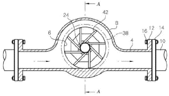
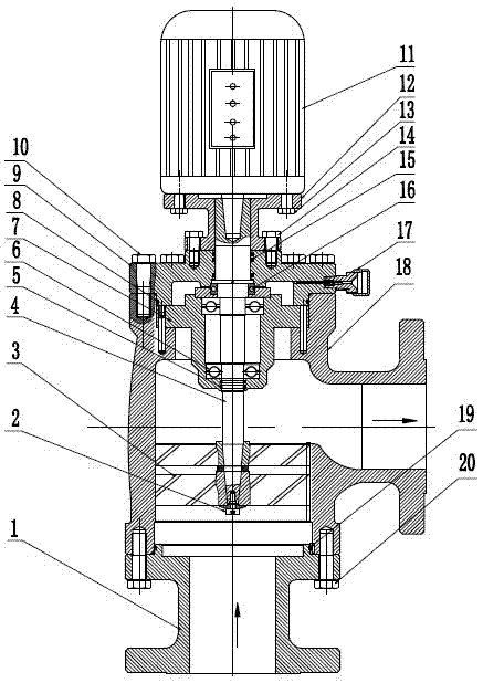
[0015] See figure 2 , including a three-way main valve body 18, the pipeline cavity at the outlet end of the main valve body 18 is bent upwards from the horizontal to the upper port, and the straight-through pipeline cavity from the upper port to the lower port is provided with a turbine 3 to drive One end of the shaft 4 is equipped with a turbine 3, the screw 2 passes through the inner taper hole of the turbine 3 and is connected with the outer cone of the drive shaft 4, and the end surface is fixed by internal thread engagement and compression.

[0016] In addition, the upper port of the main valve body 18 is equipped with a bearing seat 7 and an upper valve cover 9 in turn, and the bearing seat 7 is provided with a bearing A6, and the bearing A6 is sleeved behind the drive shaft 4, and the drive shaft 4 is equipped with a bearing B16 and then worn. Go out upper bonnet 9 central holes.

[0017] Further, the bolt A10 passes through the connection hole of the upper valve cov...


PUM


Abstract

The invention relates to a pipe flowing medium driving device, in particular to a pipe flowing medium axial-flow-type pressure driver. A pipe cavity at the outlet end of a main valve body (18) is bent upwards from the horizontal level and is communicated with an upper port. A turbine (3) is arranged in a straight-through pipe cavity from the upper port to a lower port. The turbine (3) is installed at one end of a driving shaft (4). A screw (2) penetrates through the central hole of the turbine (3) and is engaged with a hole in one end surface of the driving shaft (4) through a female thread. The pipe flowing medium axial-flow-type pressure driver has the characteristics that the structure is simple and compact, the flowing pressure energy of flowing media can be effectively converted into electric energy which can be used for driving other equipment, petroleum departments can use controlled flowing media in natural gas transmission lines as power sources to drive the driver to rotate, the power generator is driven to generate power, the problem in obtaining production and domestic electricity is solved, the original gas transmission and distribution process flow is not affected, the existing abandoned power sources are fully used, the energy is saved, the emission is reduced, the environmental protection is facilitated and the like.

Description

technical field [0001] The invention relates to a driving device for a flow medium in a pipeline, in particular to an axial-flow pressure driver for a flow medium in a pipeline. Background technique [0002] The existing generator is a mechanical device that converts other forms of energy into electrical energy. It is driven by a water turbine, steam turbine, diesel engine, gasoline engine or other power machinery, and converts the energy generated by water flow, air flow, fuel oil combustion or nuclear fission into mechanical energy. Generator, which is then converted into electrical energy by the generator. [0003] The Korean published patent technology KR10-0900782B1 also uses the pipeline flow medium to drive the impeller to rotate, and the impeller drives the shaft to rotate the mechanical structure. It uses the pipeline flow medium to drive the impeller radially, but in fact (see figure 1 ) The pressure of the flowing medium in all directions in the closed pipe is co...

Claims


Application Information

Patent Timeline
Patent Type & Authority Applications(China)
IPC IPC(8): F01D15/10F03B13/00
CPCY02B10/50
Inventor 钟桦
Owner CHONGQING MAOYU GAS EQUIP
Why Eureka
Try Eureka