Modulation ring rotor based on magnetic shielding principle

A modulation ring, principle technology, applied in the direction of magnetic circuit rotating parts, magnetic circuit shape/style/structure, etc., to achieve the effect of high mechanical strength, high mechanical strength and low loss

Active Publication Date: 2013-03-13
HARBIN INST OF TECH
View PDF11 Cites 13 Cited by
  • Summary
  • Abstract
  • Description
  • Claims
  • Application Information

AI Technical Summary

Problems solved by technology

[0008] The purpose of the present invention is to solve the problem that the existing modulating ring rotor cannot balance low loss and high mechanical strength, and provides a modulating ring rotor based on the principle of magnetic field shielding

Method used


Image

  • Modulation ring rotor based on magnetic shielding principle
  • Modulation ring rotor based on magnetic shielding principle
  • Modulation ring rotor based on magnetic shielding principle

Examples


specific Embodiment approach 1

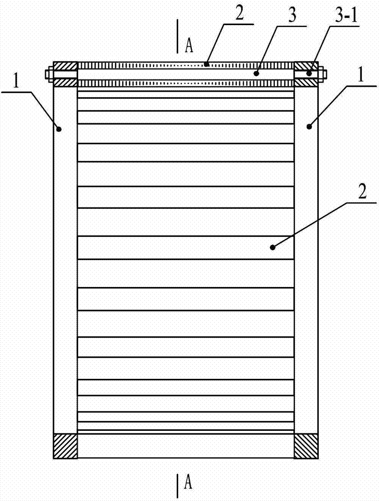
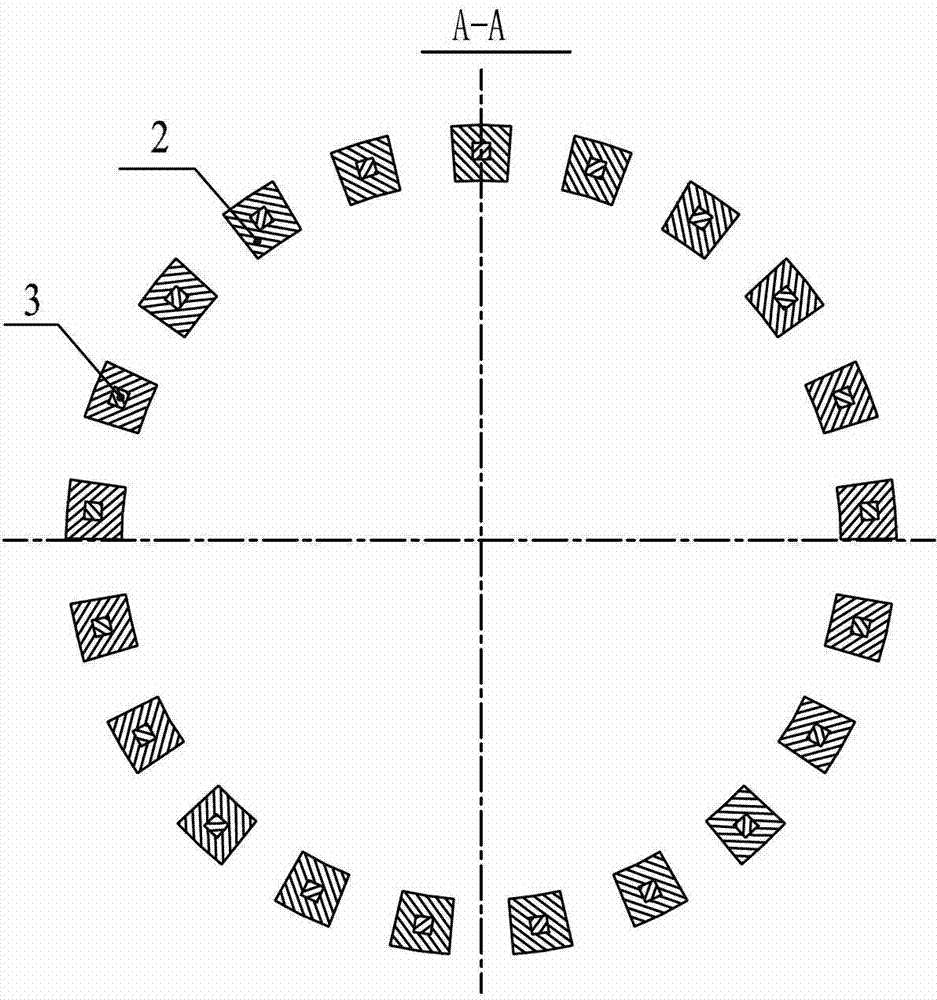
[0036] Specific implementation mode one: the following combination Figure 1 to Figure 7 Describe this embodiment, the modulation ring rotor based on the magnetic field shielding principle described in this embodiment, it includes two end rings 1, n magnetic conductive blocks 2 and n connecting rods 3,

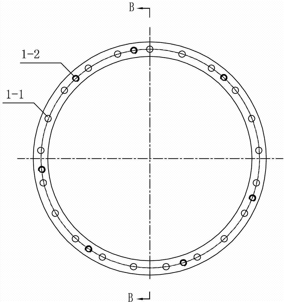
[0037] A plurality of through holes 1-1 are evenly arranged on the end surface of the end ring 1 along the circumferential direction, and a plurality of screw holes 1-2 are evenly arranged on one end surface of the end ring 1,

[0038] The two end rings 1 are arranged in parallel, and the screw holes of the end rings 1 are arranged opposite to each other, the positions of the through holes 1-1 in the two end rings 1 are opposite to each other, and n magnetic blocks are arranged between the two end rings 1 2. Each magnetic block 2 is fixed together with two end rings 1 by a connecting rod 3,

[0039] A cylindrical screw 3-1 is arranged at both ends of the shaft of the connecti...

specific Embodiment approach 2

[0048] Specific implementation mode two: the following combination Figure 8 and Figure 9 This embodiment will be described, and this embodiment will further describe the first embodiment, which also includes a strap 4, which is wound and fixed on the outer circular surface of the modulation ring rotor.

[0049] Bandage 4 is realized by glass fiber cloth tube. The modulating ring rotor of this embodiment has better mechanical reliability.

specific Embodiment approach 3

[0050] Specific implementation mode three: the following combination Figure 10 and Figure 11 This embodiment will be described. This embodiment will further describe the first embodiment, which also includes epoxy resin 5 , and the epoxy resin 5 fills the gap between the end ring 1 and the magnetic block 2 .

[0051] exist Figure 10 The air part in the middle modulation ring rotor is poured with epoxy resin to form a Figure 11 The modulating ring rotor in. The modulation ring rotor in this embodiment has higher mechanical reliability.


PUM


Abstract

The invention discloses a modulation ring rotor based on a magnetic shielding principle, belongs to the field of a permanent magnet motor, and aims at solving the problem that the existing modulation ring rotor can not consider both low loss and high mechanical strength. The modulation ring rotor comprises two end rings, n magnetic blocks and n connecting rods, wherein a plurality of through holes are uniformly formed in the end surfaces of the end rings along the periphery direction; a plurality of screw holes are uniformly formed in one end surface of the end rings; the two end rings are arranged in parallel; the screw hole sides of the end rings are arranged back to back; the positions of the through holes in the two end rings are opposite one by one; the n magnetic blocksare arranged between the two end rings; each magnetic block is fixed with the two end rings together through one connecting rod; a cylindrical screw is arranged at each end of a body of each connecting rod; the body of each connecting rod is embedded in the magnetic block; the screws at the two ends of the body of the connecting rod respectively penetrate through the through holes; and each screw is fixedly provided with a nut for clamping the end rings and the magnetic blocks.

Description

technical field [0001] The invention relates to a modulation ring rotor based on the magnetic field shielding principle, and belongs to the field of permanent magnet motors. Background technique [0002] The brushless dual-rotor motor based on the principle of magnetic field modulation has two rotors and shafts with independent rotational speeds, which can realize independent drive of two shafts. It solves the problem of lower operating efficiency, lower reliability and frequent maintenance due to the use of brush slip ring structure in the previous brushed double-rotor motor, as well as serious heating and dynamic balance problems of the rotor with armature winding. Therefore, it has broad application prospects in electric vehicles, wind power generation, torpedo propulsion and other occasions. [0003] 这种基于磁场调制原理的无刷双转子电机的工作原理已经在专利号为ZL201010274167.9、ZL201010274160.7、ZL 201010274156.0、ZL201010274135.9、ZL201010274669.1、ZL201010274337.3、ZL201010274329.9、ZL201010274325.0 desc...

Claims


Application Information

Patent Timeline
Patent Type & Authority Applications(China)
IPC IPC(8): H02K1/22
Inventor 郑萍白金刚刘勇于斌吴帆
Owner HARBIN INST OF TECH
Why Eureka
Try Eureka