Wireless charging transceiver module preparation technology and wireless charging transceiver module

A technology of wireless charging and preparation process, applied in the direction of inductor/transformer/magnet manufacturing, circuits, electrical components, etc., can solve the problems of low charging efficiency, inability to achieve the ultimate power transmission efficiency, inability to meet application requirements, etc., to avoid excessive charging. The effect of multiple magnetic flux leakage, improving charging efficiency, and improving charging efficiency

Inactive Publication Date: 2018-08-24
SHENZHEN SUNWAY COMM
View PDF16 Cites 4 Cited by
  • Summary
  • Abstract
  • Description
  • Claims
  • Application Information

AI Technical Summary

Problems solved by technology

[0007] Although the above patents have mentioned the method of reducing the magnetic loss, the process method cannot fully exert the optimal effect of this method
Please refer to image 3 , the combined structure of the traditional wireless charging receiver coil 1 and magnetic materials. The advantage of this structure is that it is simple to prepare and easy to assemble. The disadvantage is that the shielding and magnetic conduction effects of the shielding sheet cannot be fully utilized, and the power transmission efficiency cannot be maximized.
To sum up, the coil & magnetic material lamination structure used in the existing wireless charging electromagnetic shielding sheet has low charging efficiency; in addition, the existing shielding sheet structure cannot fully utilize the shielding performance of the soft magnetic material and cannot meet the application requirements

Method used


Image

  • Wireless charging transceiver module preparation technology and wireless charging transceiver module
  • Wireless charging transceiver module preparation technology and wireless charging transceiver module
  • Wireless charging transceiver module preparation technology and wireless charging transceiver module

Examples


Embodiment Construction

[0024] The present invention will be described in more detail below in conjunction with the accompanying drawings and embodiments.

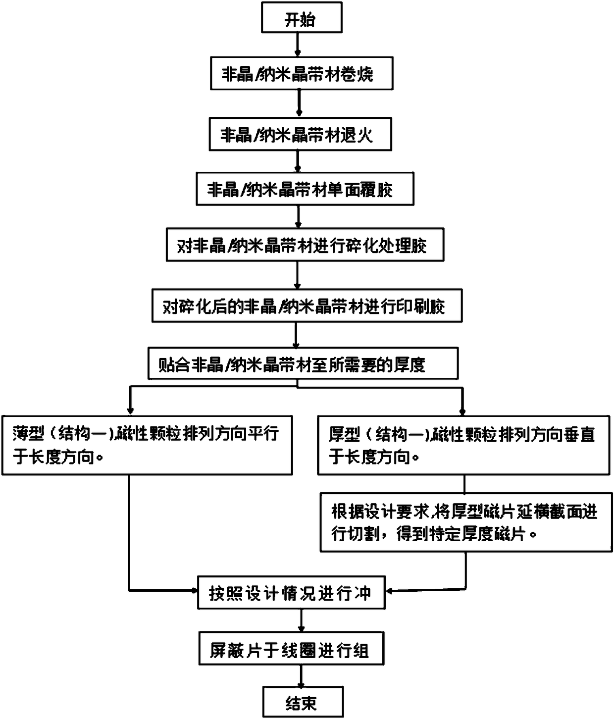
[0025] The invention discloses a preparation process of a wireless charging transceiver module, please refer to figure 1 , which includes the following steps:

[0026] Step S1, preparation of electromagnetic wave shielding sheet materials: preparing high magnetic permeability alloy strips;

[0027] Step S2, heat treatment: winding the high magnetic conductivity alloy strip to a preset size, and then putting the wound high magnetic conductivity alloy strip into a heat treatment furnace for heat treatment;

[0028] Step S3, applying single-sided adhesive: using a laminating machine to apply adhesive to one side of the heat-treated magnetically permeable alloy strip, and attaching a protective film with single-sided adhesive to the surface of the highly magnetically permeable alloy strip;

[0029] Step S4, using laser cutting or chemical etching ...


PUM

PropertyMeasurementUnit
thicknessaaaaaaaaaa

Abstract

The invention discloses a wireless charging transceiver module preparation technology. The preparation technology comprises the steps that step S1, a high magnetic conductive alloy strip is prepared;step S2, the winded high magnetic conductive alloy strip is put into a heat treatment furnace for heat treatment; step S3, single face coating is carried out on the high magnetic conductive alloy strip after heat treatment; step S4, graphic treatment is carried out on the high magnetic conductive alloy strip; step S5, the surface of the uncoated high magnetic conductive alloy strip is recoated; step S6, fitting of preset number of layers is carried out in sequence on the high magnetic conductive alloy strip, and then lamination is carried out on the magnetic sheet formed by fitting; step S7, the obtained magnetic sheet is die-cut; step S8, the die-cut magnetic sheets are fitted in sequence and then are assembled with a coil, so that the magnetic sheet and the coil are located in the same plane to obtain a wireless charging transceiver module based on the coil and the magnetic sheet. The wireless charging transceiver module preparation technology has the advantages that the coil can beembedded into a permeability magnetic material, thereby achieving power transmission and improving the power transmission efficiency of the wireless charging transceiver module.

Description

technical field [0001] The invention relates to a receiving and sending module of a wireless charging device, in particular to a preparation process of a wireless charging transceiver module and a wireless charging transceiver module. Background technique [0002] With the rapid development of science and technology and the wide application of electronic equipment, people's work and life are increasingly dependent on electronic equipment. Regarding the charging part of electronic equipment, wireless charging technology is also called inductive charging and non-contact charging. It is a new charging technology derived from wireless power transmission technology. Wireless charging technology uses near-field sensing, and the wireless charger transmits energy to the device that needs to be charged. Under normal circumstances, the energy transmitted by the capacitor is very small, which has a lot to do with the small electrode area. Therefore, to meet the power levels required ...

Claims


Application Information

Patent Timeline
Patent Type & Authority Applications(China)
IPC IPC(8): H01F41/02H01F41/00H02J50/12
CPCH01F41/005H01F41/0233H02J50/12
Inventor 康来利李家洪庞治华王磊刘开煌徐雨
Owner SHENZHEN SUNWAY COMM
Why Eureka
Try Eureka