Detachable split type bone rongeur

A rongeur and split-type technology, which is applied in the field of detachable split-type rongeurs, can solve the problems of reflective rod body, cutting, and unsmooth separation, etc., and achieve the effects of improving success rate, saving production materials, and having controllability

Active Publication Date: 2015-05-20
北京安德思考普科技有限公司
View PDF3 Cites 0 Cited by
  • Summary
  • Abstract
  • Description
  • Claims
  • Application Information

AI Technical Summary

Problems solved by technology

[0007] The object of the present invention is to provide a detachable split rongeur, which can quickly separate and cut angular bone and irregular ligaments, solve the problem of unsmooth cutting and separation using traditional cutting forceps, and also It can be disassembled and separated, has the advantages of low manufacturing cost, and can solve the problem of reflection of the rod body of traditional cutting pliers

Method used


Image

  • Detachable split type bone rongeur
  • Detachable split type bone rongeur
  • Detachable split type bone rongeur

Examples


Embodiment 1

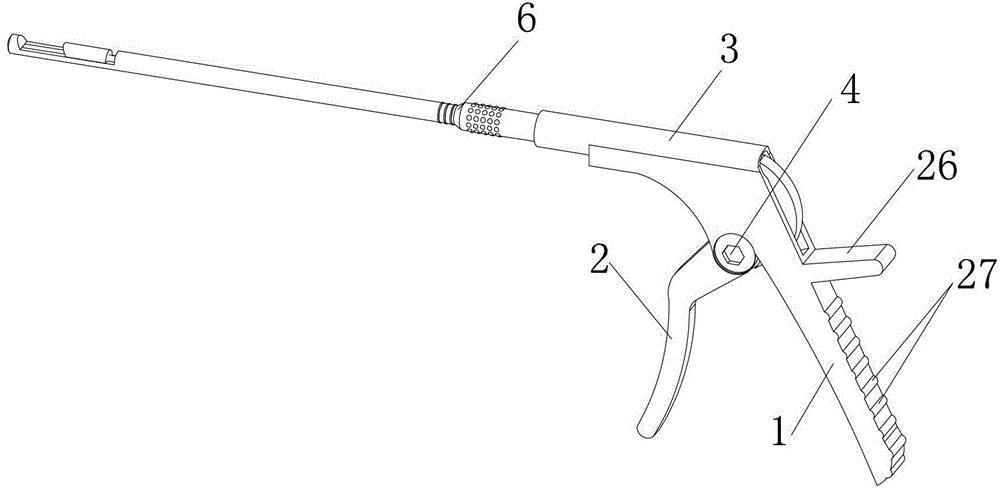
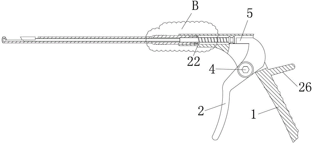
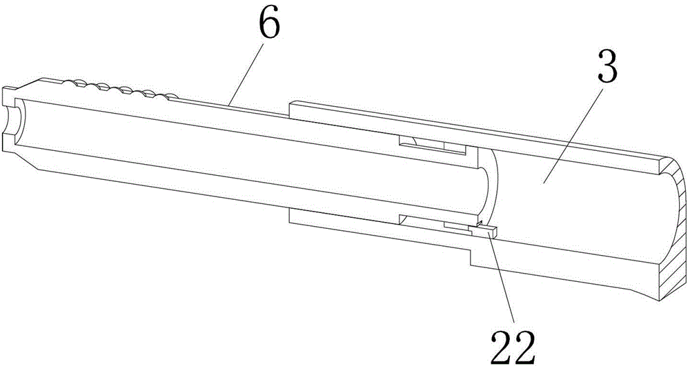
[0033] Embodiment 1 of the present invention: such as figure 1 , figure 2 with image 3 As shown, a detachable split rongeur includes a fixed handle 1, a movable handle 2, a pliers body 3, and a cutting pliers rod 6. The fixed handle 1 and the pliers body 3 are an integrated structure, and the movable handle 2 and the fixed handle 1 Through the movable connection of the shaft 4, the upper part of the movable handle 2 is located in the pliers body 3, and the top of the movable handle 2 is provided with a push rod 5; one end of the cutting pliers rod 6 is provided in the pliers body 3. An anti-slip protrusion 17 is provided on the rotating steering rod 10; a scale 18 is provided on the rod body 7 and an identification ring 19 is provided at one end of the rod body 7 and the rotating steering rod 10 connected.

[0034] The middle and upper part of the fixed handle 1 is provided with a blocking rod 26, and the outer side of the fixed handle 1 is provided with a non-slip groove 27. T...

Embodiment 2

[0038] Embodiment 2 of the present invention: such as figure 1 , figure 2 with image 3 As shown, a detachable split rongeur includes a fixed handle 1, a movable handle 2, a pliers body 3, and a cutting pliers rod 6. The fixed handle 1 and the pliers body 3 are an integrated structure, and the movable handle 2 and the fixed handle 1 Through the movable connection of the shaft 4, the upper part of the movable handle 2 is located in the pliers body 3, and the top of the movable handle 2 is provided with a push rod 5; one end of the cutting pliers rod 6 is provided in the pliers body 3. The rotating steering rod 10 is provided with anti-slip protrusions 17; the rod body 7 is provided with a scale 18, and the end connecting the rod body 7 and the rotating steering rod 10 is provided with three identification rings 19.

[0039] The middle and upper part of the fixed handle 1 is provided with a blocking rod 26, and the outer side of the fixed handle 1 is provided with a non-slip groove...

Embodiment 3

[0043] Embodiment 3 of the present invention: figure 1 , figure 2 with image 3 As shown, a detachable split rongeur includes a fixed handle 1, a movable handle 2, a pliers body 3, and a cutting pliers rod 6. The fixed handle 1 and the pliers body 3 are an integrated structure, and the movable handle 2 and the fixed handle 1 Through the movable connection of the shaft 4, the upper part of the movable handle 2 is located in the pliers body 3, and the top of the movable handle 2 is provided with a push rod 5; one end of the cutting pliers rod 6 is provided in the pliers body 3. The rotating steering rod 10 is provided with anti-skid protrusions 17; the rod body 7 is provided with a scale 18, and the end connecting the rod body 7 and the rotating steering rod 10 is provided with five identification rings 19.

[0044] The middle and upper part of the fixed handle 1 is provided with a blocking rod 26, and the outer side of the fixed handle 1 is provided with a non-slip groove 27. The...


PUM


Abstract

The invention discloses a detachable split type bone rongeur, which comprises a fixed handle (1), a movable handle (2), a rongeur body (3) and a cutting rongeur rod (6), wherein the fixed handle (1) and the rongeur body (3) are an integrated structure; the movable handle (2) and the fixed handle (1) are movably connected by a rotating shaft (4); the upper part of the movable handle (2) is located inside the rongeur body (3); a push rod (5) is arranged at the top of the movable handle (2); and one end of the cutting rongeur rod (6) is arranged inside the rongeur body (3). The detachable split type bone rongeur can quickly separate out and cut angular bones and irregular ligaments, solves the problem that the traditional cutting forceps are not smooth in cutting and separating, can be disassembled, is low in the manufacturing cost, and can solve the light reflecting problem of the traditional cutting forceps rods.

Description

Technical field [0001] The invention relates to a detachable split rongeur, which belongs to the field of medical equipment. Background technique [0002] In the prior art, when performing operations on the lumbar, thoracic, or cervical spine, it is often necessary to separate and cut angular bony or irregular ligaments. In the past, there was no special bone cutting forceps, but a general nucleus pulposus. Instead of using forceps, this makes the separation and cutting very difficult, prolongs the operation time, has poor control over the operation process, and has the problem of unclean handling of residual tissue. [0003] In order to solve the above problems, the inventor of this case has invented a bone cutting pliers, which includes a fixed handle, a movable handle, a pliers rod, a wire drawing, a pliers head and a movable cutting sheath. The movable handle is used to push and pull the wire to control cutting. The movement of the sheath can realize the cutting of bones. Alth...

Claims


Application Information

Patent Timeline
Patent Type & Authority Patents(China)
IPC IPC(8): A61B17/285
Inventor 雷东
Owner 北京安德思考普科技有限公司
Why Eureka
Try Eureka