
Lathe with automatic control function

A technology of lathes and control devices, applied in automatic lathes/semi-automatic lathes, manufacturing tools, metal processing equipment, etc., can solve problems such as unfavorable product quality, equipment cost increase, parts and equipment mechanical damage, etc. Less and more efficient work

Inactive Publication Date: 2015-02-18
ANHUI CHANGQING ELECTRONICS MACHINERY GRP
View PDF7 Cites 0 Cited by
  • Summary
  • Abstract
  • Description
  • Claims
  • Application Information

AI Technical Summary

Problems solved by technology

[0003] First, before processing, the process of fixing parts is cumbersome, which affects processing efficiency;
[0004] Second, after processing, the process of disassembling parts is cumbersome, which affects processing efficiency;
[0005] Third, after the parts are fixed, it is inevitable to cause mechanical damage to the parts and equipment during the processing, which is not conducive to the improvement of product quality and will affect the service life of the equipment
[0006] In addition, in the process of processing, the scrap rate remains high, and the processing accuracy can only depend on the familiarity of the technicians with the operation. With the emergence of numerical control technology, the above problems have been solved, but the cost of equipment has also been greatly increased, especially For some simple mechanical processing equipment, it is not advisable to use numerical control equipment to improve efficiency and processing accuracy, and it needs to be improved urgently

Method used


Image

  • Lathe with automatic control function

Examples


Embodiment 1

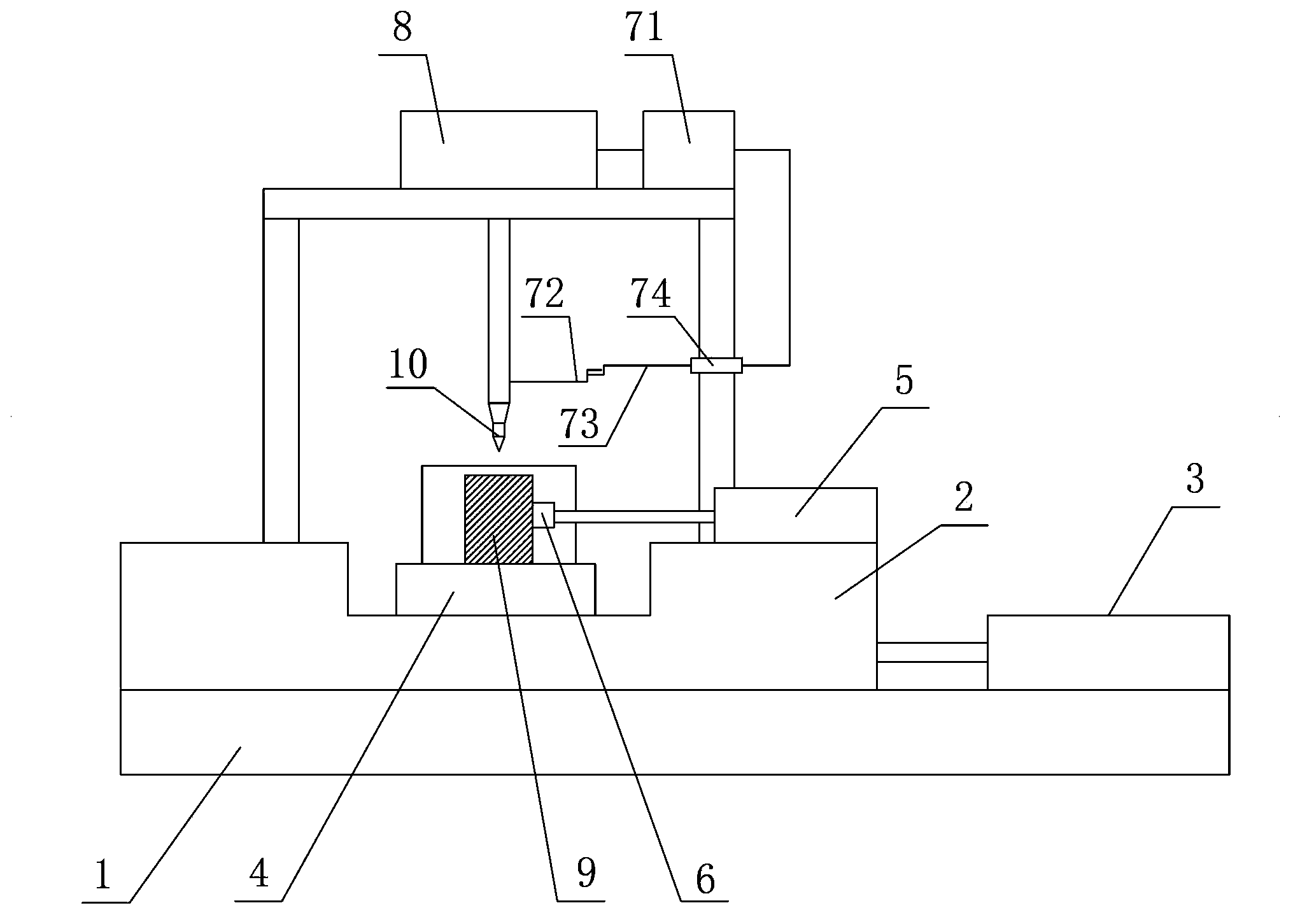
[0015] A processing lathe with automatic control is proposed, including a base 1; a workbench 2, which is movably connected to the base 1; a first power device 8, which is fixed to the base 1, and can drive the tool 10 up / down, and the tool 10 is fixedly connected to the first Contact 72; the second power unit 3, fixed base 1, can drive the workbench 2, so that the limit block 4 fixed on the workbench 2 is close to / away from the bottom of the tool 10; the third power unit 5, fixed workbench 2. It can drive the plug 6 close to / away from the side of the limit block 4; the pressure sensing transmission device 74 includes the sensing part 73, and the first contact 72 is linked with the sensing part 73; the control device 71 controls the opening of the first power device 8 / Close; when the control device 71 receives the pressure information from the pressure-sensing transmission device 74 , the control device 71 controls the first power device 8 to be closed. An accommodating groov...


PUM


Abstract

The invention discloses a lathe with an automatic control function. The lathe comprises a base, a worktable, a first power device, a second power device, a third power device, a pressure sensing and transmission device and a control device, wherein the worktable is movably connected with the base; the first power device is fixedly arranged on the base and can drive a cutter to move up and down, and the cutter is fixedly connected with a first contact; the second power device is fixedly arranged on the base and can drive the worktable to enable a limiting block which is fixedly arranged on the worktable to get close to and or far away from a position right belowunder the cutter; the third power device is fixedly arranged on the worktable and can drive an ejection head to get close to and or far away from one side of the limiting block; the pressure sensing and transmission device comprises a sensing part and the first contact is connected with the sensing part; the control device is used for controlling the startup and the shutdown of the first power device; and when the control device receives pressure information coming from the pressure sensing and transmission device, the control device controls the first power device to be shut down. The lathe with the automatic control function has the advantages that the machining efficiency is high, the quality of the machined products is good, the service life of equipment is long, the upward movement and the downward movement of the cutter are automatically controlled, and not only can the investment be reduced, but also the effect of a numerical control machine can be achieved.

Description

technical field [0001] The invention relates to a processing lathe with automatic control. Background technique [0002] Processing lathes with automatic control are widely used, including presses, milling machines, etc. When processing parts, the parts first need to be fixed. The existing method is to fix the parts by rivets, and the way of fixing parts by rivets exists The following questions. [0003] First, before processing, the process of fixing parts is cumbersome, which affects processing efficiency; [0004] Second, after processing, the process of disassembling parts is cumbersome, which affects processing efficiency; [0005] Third, after the parts are fixed, it is inevitable to cause mechanical damage to the parts and equipment during the processing, which is not conducive to the improvement of product quality and will affect the service life of the equipment. [0006] In addition, in the process of processing, the scrap rate remains high, and the processing a...

Claims


Application Information

Patent Timeline
Patent Type & Authority Patents(China)
IPC IPC(8): B23B7/00
Inventor 吴长青
Owner ANHUI CHANGQING ELECTRONICS MACHINERY GRP
Learn More