

Construction method for treating vehicle jump at bridge head in highway
A bridge head jumping and construction method technology, which is applied in bridge engineering and road engineering fields, can solve problems such as the inability to solve the compactness of the abutment back, the limitation of the use of large compactors, and the narrow construction space of the abutment back, etc., to reduce the settlement difference , low cost, stable foundation effect
- Summary
- Abstract
- Description
- Claims
- Application Information
AI Technical Summary
Problems solved by technology
Method used
Image

Examples
Embodiment Construction
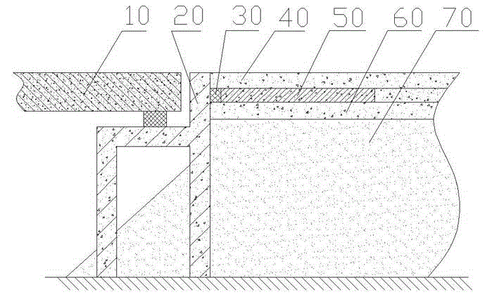
[0022] see figure 1 , the construction method of the present invention's control highway bridge head jumping, comprises subgrade treatment, base course treatment and road surface construction, specifically comprises the following steps.
[0023] Step A. Use plain soil or light materials to fill in layers at the back of the abutment. The compacted thickness of each layer shall not exceed 20cm. The compaction degree at the optimum moisture content shall be greater than 95%. The surface is tamped with a powerful tamping machine to form a stable platform back subgrade 70. The lightweight material refers to fillers with low density. Due to the low density of fillers, the settlement caused by the self-weight of the bridge head is small, which can greatly reduce the pressure on the foundation, thereby helping to solve the technical problem of bridge head jumping.
[0024] The compactness of tamping is greater than 100% at the optimum moisture content. In the prior art, low compactn...
PUM
| Property | Measurement | Unit |
|---|---|---|
| Strength | aaaaa | aaaaa |
| Thickness | aaaaa | aaaaa |
Abstract
Description
Claims
Application Information