Non-energy consumption centralized utilization system of high-rise building waste water

A high-rise building, no energy consumption technology, used in buildings, water supply installations, water supply installations, etc., can solve the problems of not being effectively promoted, high price, and high energy consumption, so as to alleviate the problem of urban water shortage and save water resources. , the effect of strong compatibility

Inactive Publication Date: 2013-03-20
CHONGQING UNIV
View PDF6 Cites 3 Cited by
  • Summary
  • Abstract
  • Description
  • Claims
  • Application Information

AI Technical Summary

Problems solved by technology

Reclaimed water needs a large amount of transmission and distribution pipeline network, and the reclaimed water pipeline network requires huge investment, construction is also very difficult, and the entire utilization process consumes a lot of energy. These are the main bottlenecks restricting the development of the reclaimed water reuse industry
Wastewater utilization devices in households and student dormitories are mainly divided into utilization on the same floor and utilization on different floors. The devices used on the same floor need other energy-consuming devices such as water pumps to provide power, and the price is very high. There are many versions and relatively mature technologies, but because of the flaws in the design ideas, they have not been effectively promoted so far

Method used


Image

  • Non-energy consumption centralized utilization system of high-rise building waste water
  • Non-energy consumption centralized utilization system of high-rise building waste water
  • Non-energy consumption centralized utilization system of high-rise building waste water

Examples


Embodiment Construction

[0019] The present invention will be described in further detail below in conjunction with the accompanying drawings and specific embodiments.

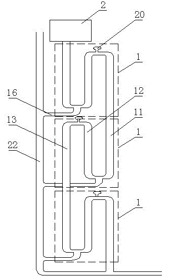
[0020] Such as figure 1 As shown, the non-energy intensive utilization system of high-rise building wastewater includes a rainwater tank 2 and at least two double U-shaped pipe units 1 arranged sequentially from top to bottom. The rainwater tank 2 is arranged on the roof for collecting rainwater, and the flow rate of the rainwater tank 2 is controlled by a gate valve. The rainwater tank 2 is provided with an overflow port, and a gate valve is provided at the connection part with the double U-shaped pipe unit 1. The gate valve can be adjusted to control the flow of rainwater entering the double U-shaped pipe unit 1, so as to prevent the heavy rain from causing damage to the double U-shaped pipe unit 1. The U-shaped pipe unit causes strong impact and damages the pipe.

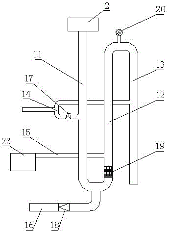
[0021] The structure of each double U-shaped pipe unit 1 is as fo...


PUM


Abstract

The invention discloses a non-energy consumption centralized utilization system of high-rise building waste water comprising a rainwater tank and at least two double U-shaped pipe units which are arranged in sequence from top to bottom; each double U-shaped pipe unit comprises a water collection pipe, a water storage pipe, an overflow pipe, a Y-shaped three-way pipe, a water outlet pipe, a sewage pipe and a purification device; the top of the water collection pipe of the top double U-shaped pipe unit of all the double U-shaped pipe units is communicated with the rainwater tank; and the overflow pipe of the previous double U-shaped unit is communicated with the water collection pipe of the next double U-shaped pipe unit. The Y-shaped three-way pipes in the system are connected with partial domestic waste water in a residential building, so that the partial domestic waste water of the residential building and the rainwater in a balcony can be collected, flow through the double U-shaped pipe units, are purified and flow into a squatting pan water tank, and finally are used for flushing a toilet. According to the system, the collection, the purification, the storage, the utilization and the discharge of water can be realized, so that the waste water of a plurality of floors is collected simultaneously and is supplied to households to use in a centralized way, and the system is perfectly butted with an existing pipe network and has high compatibility.

Description

technical field [0001] The invention relates to a waste water utilization system, in particular to a high-rise building waste water centralized utilization system without energy consumption. Background technique [0002] At present, there are many devices and technologies for wastewater utilization. Commercially, it is called reclaimed water reuse. Reclaimed water reuse refers to the sewage and cooling water that have been used in people’s lives or discharged from production activities in civil or construction communities, and are collected, treated, advanced treated, and transported. Matching and other technical measures are reused in buildings or building areas, so as to achieve the purpose of saving water. Reclaimed water needs a large amount of transmission and distribution pipeline network, and the reclaimed water pipeline network requires huge investment, construction is also very difficult, and the entire utilization process consumes a lot of energy. These are the ma...

Claims


Application Information

Patent Timeline
Patent Type & Authority Applications(China)
IPC IPC(8): E03B3/02E03B1/04E03B11/12E03C1/12E03C1/122
CPCY02A20/108
Inventor 罗康江如芸王志勇刘鑫宋猛利龙建崔军吴志远胡静飞
Owner CHONGQING UNIV
Why Eureka
Try Eureka