Downhole multifunctional personnel location distress system

A personnel positioning and multi-functional technology, applied in the direction of reducing energy consumption, advanced technology, mining equipment, etc., can solve the problems of RFID reading and writing speed limitations, low positioning accuracy, and distribution density limitations of positioning accuracy, so as to improve real-time performance and equipment The effect of loud noise and long distance of noise propagation

Inactive Publication Date: 2013-03-20
CHINA UNIV OF MINING & TECH (BEIJING)
View PDF7 Cites 14 Cited by
  • Summary
  • Abstract
  • Description
  • Claims
  • Application Information

AI Technical Summary

Problems solved by technology

[0004] 1. The positioning accuracy is low, and the positioning accuracy is limited by the distribution density of the readers. It can only achieve regional positioning, and cannot achieve accurate positioning with an error of a few meters;
[0005] 2. It is easy to miss reading, and due to the limitation of RFID reading and writing speed, it cannot handle the situation where multiple people pass through the card reading system at the same time.
[0007] 1. The transmission loss model of the wireless signal is greatly affected by the environment. Zigbee uses the field strength positioning algorithm, which is subject to large interference, so it is easy to cause inaccurate positioning;
[0008] 2. The hardware positioning engine inside the Zigbee communication chip is suitable for a plane positioning environment. The underground i

Method used


Image

  • Downhole multifunctional personnel location distress system
  • Downhole multifunctional personnel location distress system
  • Downhole multifunctional personnel location distress system

Examples


Embodiment Construction

[0037] The present invention will be further described below in conjunction with the accompanying drawings and specific embodiments.

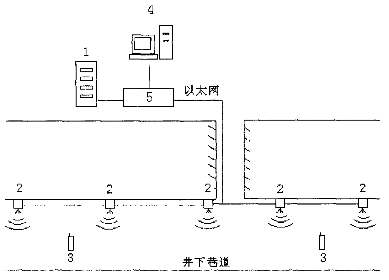
[0038] like figure 1 As shown, the underground wireless communication system:

[0039] The underground multifunctional personnel positioning and calling system includes: a positioning server (1), a wired communication subsystem, and a wireless communication base station (2). The wired communication subsystem is the backbone of the entire positioning system, and the wired communication subsystem uses optical fiber as the main transmission medium. The wired communication subsystem also includes network management equipment such as an optical splitter and a wireless switch (5). A wireless communication base station (2) is installed at a certain distance underground, and the wireless communication base station is connected to a server on the well through an optical fiber. The main function of the wireless communication base station is WI-FI wire...


PUM


Abstract

The invention discloses a downhole multifunctional personnel location distress system which comprises a location server, a monitoring terminal, a wire communication subsystem, wireless communication base stations and a distress calling device. The wire communication subsystem mainly comprises optical fibers, an optical splitter and a wireless switch. Each wireless communication base station comprises an explosion-proof box, a power supply, a standby battery, a wireless access device, an antenna isolator and antennas. The distress calling device comprises an acquisition subsystem, a location subsystem, a communication subsystem, a display subsystem, a control subsystem and a storage subsystem. The wireless communication base stations are arranged in the pit at intervals and are connected with the wireless switch and the location server through the optical fibers. The distress calling device and the wireless communication base stations are in bidirectional communication based on a wireless mode. The distress calling device can be located accurately. The downhole multifunctional personnel location distress system can be used to monitor a person using the distress calling device, has multiple distress calling functions, can support search-and-rescue when existing communication facilities are damaged and do not work, and is a synthetic system integrating mine personnel tracking and locating, dispatching management, and distress call and search-and-rescue after disasters.

Description

technical field [0001] The invention relates to an underground multifunctional personnel positioning and calling for help system. The invention specifically relates to technical fields such as wireless communication, wireless positioning, and signal processing. Background technique [0002] Downhole personnel positioning is an important measure for safe production. Over the years people have adopted various methods to detect the position of underground personnel. [0003] At present, the actual use is mainly based on radio frequency identification technology (RFID). RFID uses radio frequency to carry out non-contact two-way communication to achieve the purpose of identification and exchange data. Different from other contact identification technologies, the RFID system can realize automatic identification and position monitoring of people or objects in different states without contact between the radio frequency card and the reader. A typical radio frequency identificatio...

Claims


Application Information

Patent Timeline
IPC IPC(8): E21F17/18H04W64/00
CPCY02D30/70
Inventor 孙继平刘毅
Owner CHINA UNIV OF MINING & TECH (BEIJING)
Why Eureka
Try Eureka