Multi-stage sleeve shaft transmission device

A technology of a transmission device and a sleeve shaft is applied in the field of optical fiber rings, which can solve the problems that the optical fiber rings cannot be separated from manual operation, the optical fiber rings are not neatly arranged, and the equipment structure is simple, so as to achieve convenient human-computer interaction, low cost, and simple mechanical structure. Effect

Active Publication Date: 2013-03-20
武汉长盈通光电技术股份有限公司
View PDF9 Cites 0 Cited by
  • Summary
  • Abstract
  • Description
  • Claims
  • Application Information

AI Technical Summary

Problems solved by technology

[0004] At present, domestic optical fiber winding technology is still immature, and most of the equipment is simple in structure and incomplete in function, so the winding of optical fiber ring cannot be separated from manual operation.
For a precision device such as a fiber optic ring, a slight vibration may cause the fiber ring to be irregularly arranged, over-tensioned, or even broken. Therefore, the equipment and process around the ring directly determine the performance of the fiber optic ring.

Method used


Image

  • Multi-stage sleeve shaft transmission device
  • Multi-stage sleeve shaft transmission device
  • Multi-stage sleeve shaft transmission device

Examples


Embodiment Construction

[0014] Specific embodiments of the present invention will be described in further detail below in conjunction with the accompanying drawings.

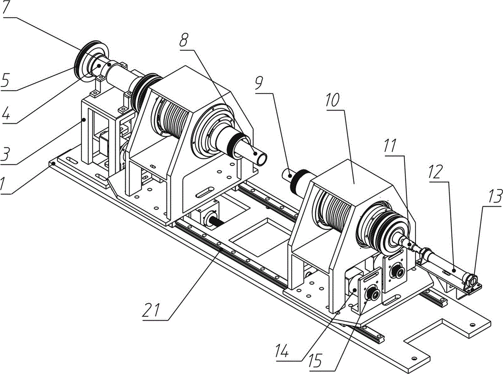
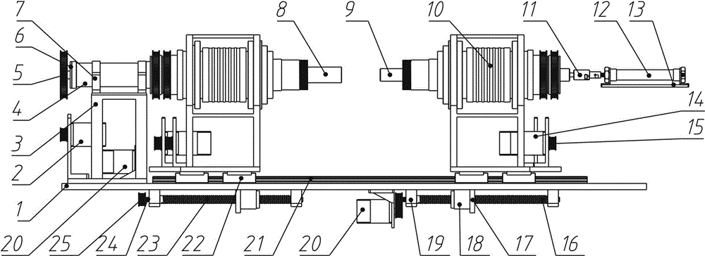
[0015] Such as figure 1 and figure 2 As shown, a multi-stage sleeve shaft transmission device of the present invention mainly includes a base plate 1 connected to an external frame, a pair of sleeve shaft mechanisms 10 , a main transmission shaft 8 and an auxiliary transmission shaft 9 . The base plate 1 is connected with the external frame and is the basis of the whole transmission device. Two linear slide rails 21 are arranged on the base plate 1, and a pair of bushing mechanisms 10 are installed on the linear slide rails 21 through linear slide blocks 22 provided at the bottom respectively. The bottom surface of the base plate 1 is provided with two sets of shaft drive mechanisms for respectively driving each shaft mechanism 10 to move along the linear slide rail 21 . The main drive shaft 8 and the auxiliary drive shaft 9 are re...


PUM


Abstract

The invention discloses a multi-stage sleeve shaft transmission device, which comprises a base plate connected with an external stander, a pair of sleeve shaft mechanisms, a main transmission shaft and an auxiliary transmission shaft, wherein a linear sliding rail is arranged on the base plate; the sleeve shaft mechanisms are respectively arranged on the linear sliding rail through linear sliding blocks; a sleeve shaft driving mechanism is arranged on the base plate; the main transmission shaft and the auxiliary transmission shaft are respectively arranged on the sleeve shaft mechanisms and are coaxially and oppositely arranged; the sleeve shaft mechanisms have the same structure and are arranged oppositely; each sleeve shaft mechanism comprises a sleeve shaft mounting bracket; a sliding ring lining is arranged on the sleeve shaft mounting bracket through a bearing; a conductive sliding ring is sleeved outside the sliding ring lining; a middle shaft sleeve is inserted into the sliding ring lining; a sleeve shaft first synchronous belt wheel and a sleeve shaft second synchronous belt wheel are arranged at one end of the middle shaft sleeve; the main transmission shaft is driven to rotate by a first servo motor on the base plate; a cylinder is arranged at the rear end of the sleeve shaft mechanism with the auxiliary transmission shaft; and two second servo motors are respectively arranged on each sleeve shaft mounting bracket and are respectively used for driving the sleeve shaft first synchronous belt wheel and the sleeve shaft second synchronous belt wheel.

Description

technical field [0001] The invention relates to an optical fiber ring in an optical fiber sensor such as an optical fiber gyroscope, in particular to a multi-stage sleeve shaft transmission device, which can cooperate with various rotating ring mechanisms to wind the optical fiber ring. Background technique [0002] The fiber optic gyroscope is a high-precision inertial sensor that measures the inertial rotation rate of space. It was born in 1976. Because of its small size, light weight, high precision, fast start-up, large dynamic range, and no mechanical rotation structure, it has been widely used in various fields such as robots, ships, aircraft, and missiles. [0003] As the core part of the fiber optic gyroscope's sensing, the basic requirement for the fiber optic ring is a larger extinction ratio and better reciprocity, because its performance directly affects the measurement accuracy of the fiber optic gyroscope. There are many winding methods for optical fiber rings...

Claims


Application Information

Patent Timeline
Patent Type & Authority Applications(China)
IPC IPC(8): G01C19/72
Inventor 李家乐郭伟华杨娟李宏周红伟曲勇军汪洪海皮亚斌
Owner 武汉长盈通光电技术股份有限公司
Why Eureka
Try Eureka