Current clamp and power quality monitoring device

A technology of power quality monitoring and current clamp, which is applied to measuring devices, measuring current/voltage, measuring electrical variables, etc., and can solve the problem that the AC and DC components of grounded steel plates at the center point of large transformers cannot be measured at the same time.

Inactive Publication Date: 2015-04-22
NINGXIA ELECTRIC POWER RES INST +2
View PDF7 Cites 0 Cited by
  • Summary
  • Abstract
  • Description
  • Claims
  • Application Information

AI Technical Summary

Problems solved by technology

[0008] Aiming at the problem in the related technology that the AC and DC components of the large-scale transformer center-point grounded steel plate cannot be measured at the same time, so that it is impossible to conduct research on the DC bias of the transformer based on the AC and DC components of the transformer center-point grounding, no effective solution has been proposed so far. Therefore, the main purpose of the present invention is to provide a current clamp and power quality monitoring device to solve the above problems

Method used


Image

  • Current clamp and power quality monitoring device
  • Current clamp and power quality monitoring device
  • Current clamp and power quality monitoring device

Examples


Embodiment Construction

[0025] It should be noted that, in the case of no conflict, the embodiments in the present application and the features in the embodiments can be combined with each other. The present invention will be described in detail below with reference to the accompanying drawings and examples.

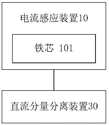
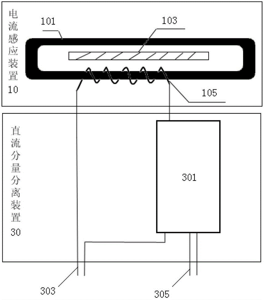
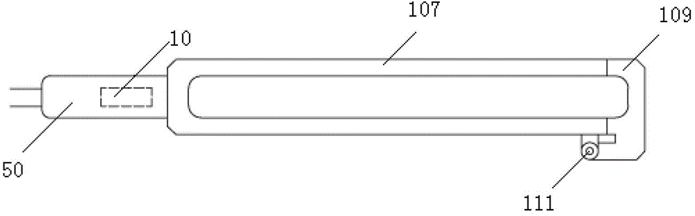
[0026] figure 1 is a schematic structural diagram of a current clamp according to an embodiment of the present invention. figure 2 is a schematic diagram of the working principle of the current clamp according to the embodiment of the present invention. image 3 is a detailed structural schematic diagram of a current clamp according to an embodiment of the present invention.

[0027] Such as figure 1 As shown, the current clamp provided by the present invention includes: a current induction device 10, including an iron core 101, the iron core 101 has a cavity matched with the measurement body, and electromagnetic induction is generated when the measurement body passes through the cavity, an...


PUM


Abstract

The invention discloses a current clamp and a power quality monitoring device. The current clamp comprises a current induction device which comprises an iron core and a direct current component separating device, wherein the iron core is provided with a cavity matched with a measurement main body; when the measurement main body passes through the cavity, the electromagnetic induction is generated; the current induction device acquires grounding current signals in the measurement main body through the electromagnetic induction; and the direct current component separating device is connected with the current induction device to separate the alternating current from the direct current in the grounding current signals, so as to obtain and output the direct current component signal and the alternating current component signal. By virtue of the current clamp and the power quality monitoring device, the alternating current signal and the direct current signal of the grounding current at the transformer center point are synchronously measured, so that the research on the grounding direct current magnetic bias and the monitor of the power quality at the transformer center point can be performed according to the synchronously measured data of the alternating current and the direct current in the grounding current at the transformer center point.

Description

technical field [0001] The invention relates to the field of electric equipment, in particular to a current clamp and a power quality monitoring device. Background technique [0002] A large DC will be generated in the transformer winding running online. We call this phenomenon of DC current in the AC current as the current bias phenomenon. The DC bias phenomenon in the transformer winding can be caused by the following two reasons: [0003] (1) The geomagnetic "storm" generated by the interaction between the dynamic change of the solar plasma wind and the geomagnetic field. The change of the geomagnetic field will induce a potential gradient on the earth's surface, and its magnitude depends on the ground conductivity and the severity of the geomagnetic storm. When this low-frequency electric field with a certain duration acts on a power transformer whose neutral point is grounded, it will The geomagnetic induction current induced in the winding has a frequency between 0.01...

Claims


Application Information

Patent Timeline
Patent Type & Authority Patents(China)
IPC IPC(8): G01R19/00G01R31/00
Inventor 黄永宁张爽张展樊益平张春宁焦龙
Owner NINGXIA ELECTRIC POWER RES INST
Why Eureka
Try Eureka