Reflective array antenna

A reflectarray antenna, antenna technology, applied in the field of communication

Active Publication Date: 2013-03-20
KUANG CHI INNOVATIVE TECH +1
View PDF2 Cites 7 Cited by
  • Summary
  • Abstract
  • Description
  • Claims
  • Application Information

AI Technical Summary

Problems solved by technology

[0005] The technical problem to be solved by the present invention is to provide a reflective array antenna for the defect that the size of

Method used


Image

  • Reflective array antenna
  • Reflective array antenna
  • Reflective array antenna

Examples


Embodiment Construction

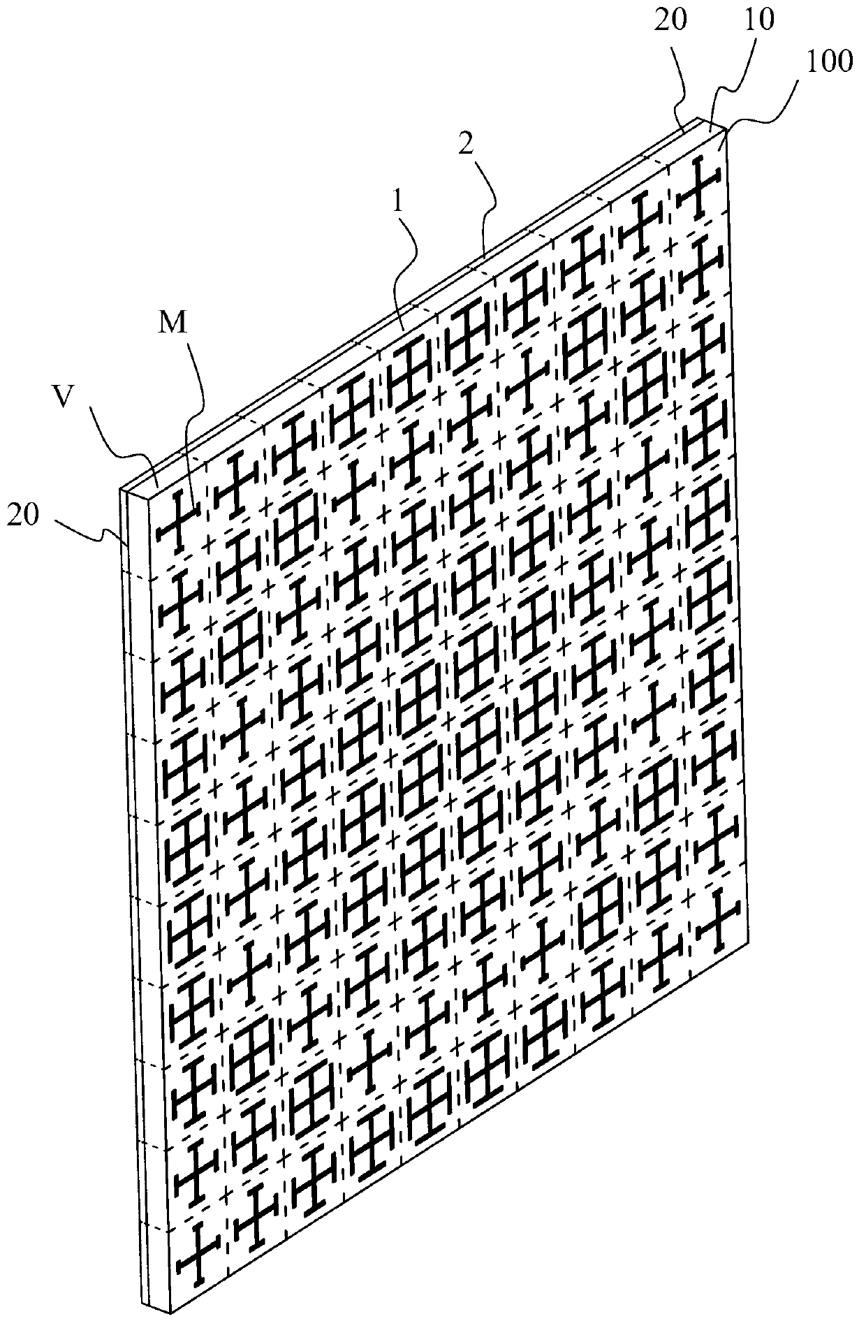
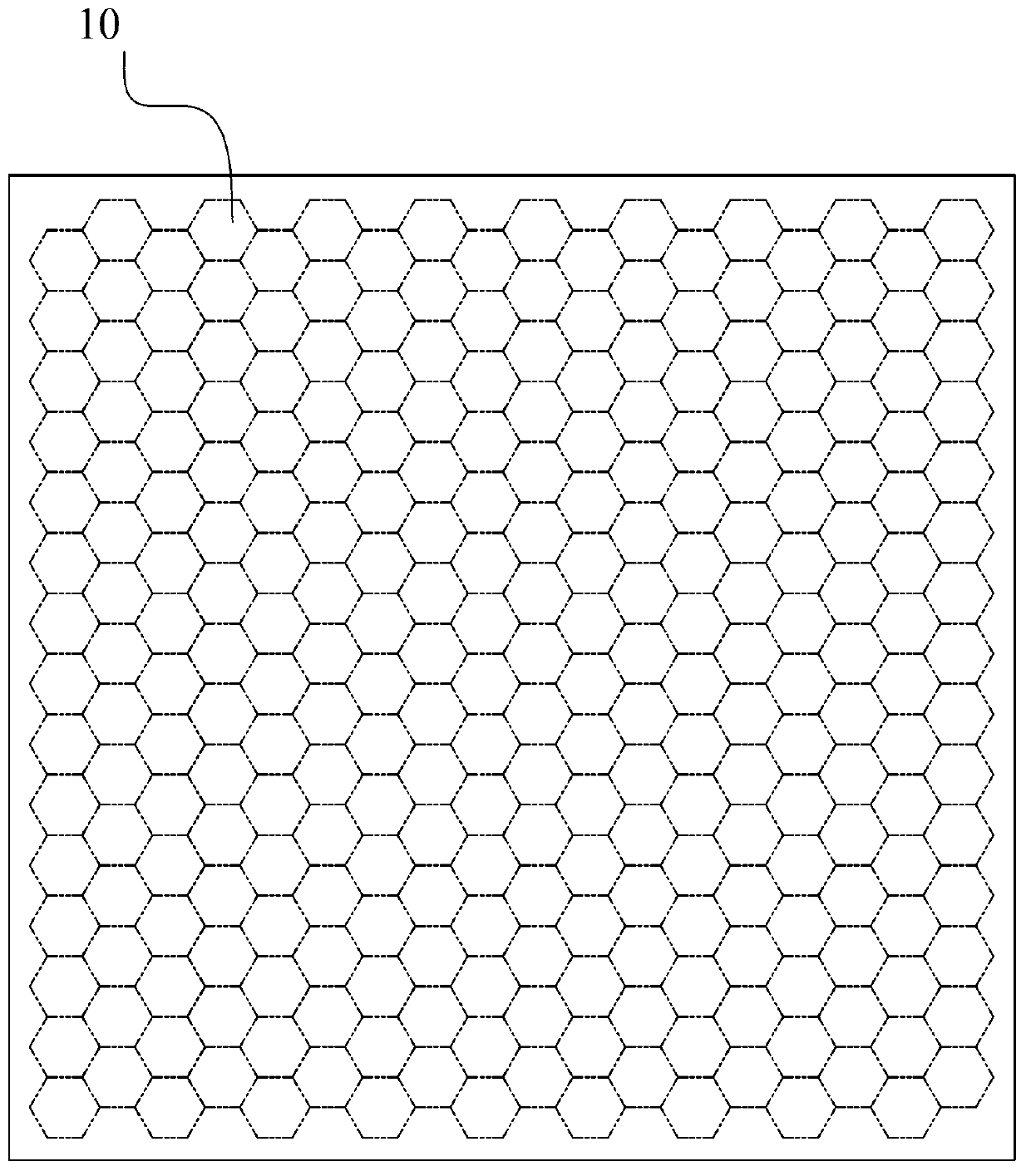
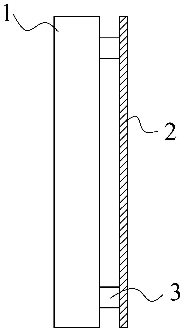
[0072] Please refer to figure 1 , figure 1 It is a schematic diagram of a three-dimensional structure of a preferred embodiment of the reflectarray antenna of the present invention. figure 1 Among them, the reflectarray antenna includes a functional board 1 for beam modulation of incident electromagnetic waves; the functional board 1 includes two or more functional board units 10 with a phase shifting function; the functional board unit 10 includes a substrate A unit V and at least one artificial structural unit M disposed on one side of the substrate unit V that generates an electromagnetic response to incident electromagnetic waves;

[0073] The reflective layer 2 is used to reflect electromagnetic waves and is arranged on the opposite side of the functional board 1 to the artificial structural unit M;

[0074] The distance between the geometric centers of two adjacent functional board units 10 is less than one-seventh of the wavelength of the incident electromagnetic wave...


PUM

PropertyMeasurementUnit
Widthaaaaaaaaaa
Thicknessaaaaaaaaaa
Thicknessaaaaaaaaaa

Abstract

The invention provides a reflector of a reflective array antenna which comprises a function board and is used for beam modulating of incidence electromagnetic wave. The function board comprises two or more function board units with a phase shift function. The function board unit comprises a base board unit, at least one artificial structure unit and a reflecting layer, wherein the at least one artificial structure unit is arranged on one side of the base board unit and generates electromagnetic response to the incidence electromagnetic wave, the reflecting layer is used for reflecting electromagnetic wave and is arranged on one side, opposites to the artificial structure unit, of the function board. Distance between two geometric centers of the two adjacent function boards is less than one seventh of wavelength of the incidence electromagnetic wave. According to the reflective array antenna, the technical bias generally believed by technical personnel that demand can not be met after the size of the phase shift unit is decreased to one sixth of the wavelength is overcome.

Description

technical field [0001] The present invention relates to the communication field, and more specifically, relates to a reflection array antenna. Background technique [0002] The reflectarray antenna is a planar array composed of a large number of microstrip patch units printed on a grounded dielectric substrate. The incident mechanism is: after the electromagnetic wave emerges from the feed source, it reaches each microstrip patch unit along different transmission paths, and the difference in the length of the transmission path will cause different spatial phase delays in the incident field received by each microstrip patch unit. , by rationally designing each microstrip patch unit to make appropriate phase compensation for the incident field, so that the reflected field forms the required phase wavefront on the antenna aperture surface. [0003] In the traditional reflectarray theory, it is generally required that the size of the phase-shifting unit be smaller than half the...

Claims


Application Information

Patent Timeline
IPC IPC(8): H01Q19/10H01Q21/00H01Q3/46H01Q1/38
Inventor 刘若鹏季春霖殷俊
Owner KUANG CHI INNOVATIVE TECH
Why Eureka
Try Eureka