System and method for controlling direct power of open-winding brushless double-fed wind driven generator
A technology of wind turbines and doubly-fed generators, which is applied in the directions of wind turbines, wind turbine combinations, and wind energy generation, can solve the problems of sensitive parameters of the flux linkage observer, high cost, and poor real-time performance of the control system.
- Summary
- Abstract
- Description
- Claims
- Application Information
AI Technical Summary
Problems solved by technology
Method used
Image

Examples
Embodiment Construction
[0044] The present invention is described in detail below in conjunction with accompanying drawing:
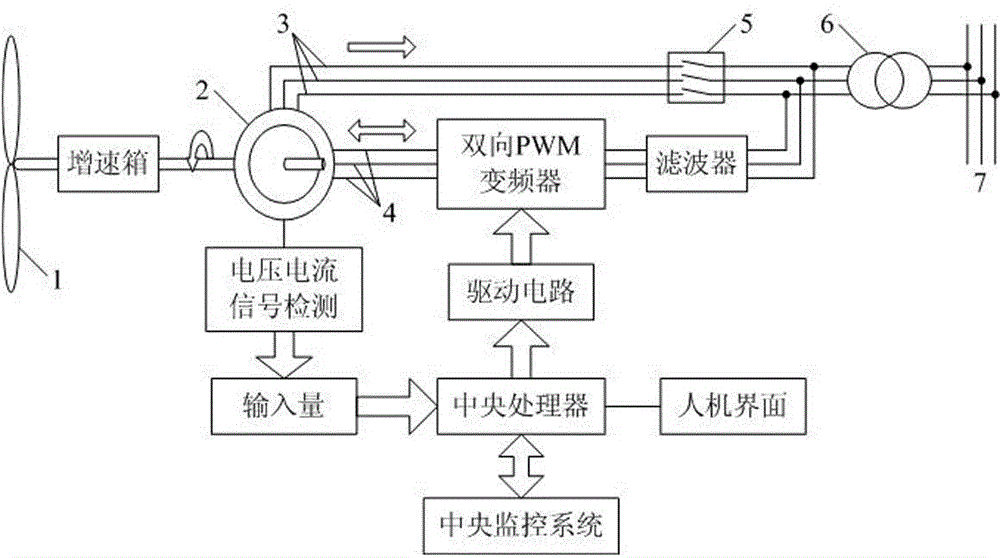
[0045] like figure 1 As shown, the present invention provides a direct power control system of a composite rotor open-winding brushless doubly-fed wind generator, the system mainly includes a wind turbine 1, a brushless doubly-fed wind generator 2, a bidirectional PWM frequency converter and a central processing unit; The wind turbine 1 is connected to the brushless doubly-fed wind turbine 2 through the gearbox, and the brushless doubly-fed wind generator 2 is connected to the bidirectional PWM inverter on the one hand, and connected to the transformer 6 through the grid-connected switch 5 on the other hand. On the one hand, it is connected to the central processing unit through the voltage and current signal detection unit and the input unit in turn; the two-way PWM frequency converter is connected to the transformer 6 through the filter, and the transformer 6 is connected t...
PUM
 Abstract
Description
Claims
Application Information
 - Generate Ideas
- Intellectual Property
- Life Sciences
- Materials
- Tech Scout
- Unparalleled Data Quality
- Higher Quality Content
- 60% Fewer Hallucinations
Browse by: Latest US Patents, China's latest patents, Technical Efficacy Thesaurus, Application Domain, Technology Topic, Popular Technical Reports.
© 2025 PatSnap. All rights reserved.Legal|Privacy policy|Modern Slavery Act Transparency Statement|Sitemap|About US| Contact US: help@patsnap.com