Data center cooling solution
A data center and solution technology, applied in the direction of cooling/ventilation/heating transformation, can solve the problems of difficult upgrading of hardware equipment, expensive initial cost of connecting pipes for water pump radiators, etc., to achieve simple and reasonable design, good energy-saving effect, and convenient use. Effect
- Summary
- Abstract
- Description
- Claims
- Application Information
AI Technical Summary
Problems solved by technology
Method used
Image

Examples
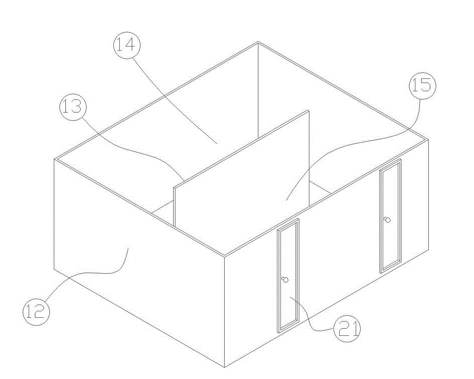
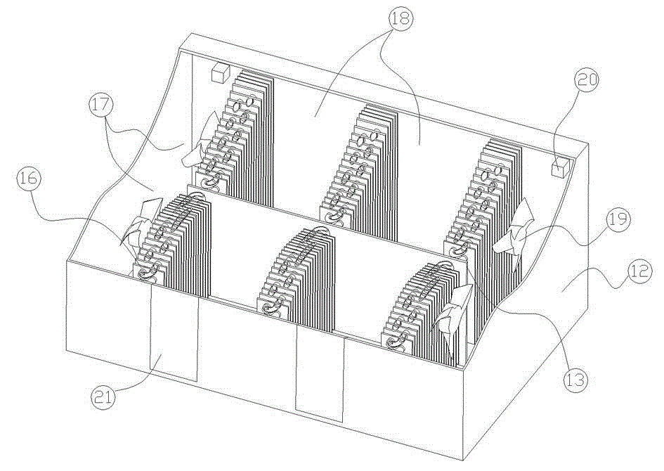
Embodiment 1
[0030] Such as Figure 4 The work flow diagram of the first scheme of the present invention is shown, large compressor (3), condenser (2), check valve (83), liquid storage tank (6), check valve (84), throttling The valve (5), the evaporator (1) and the solenoid valve (71) are connected in the order listed above through the connecting pipes to form a heat pump circulation circuit; the one-way valve (81), the liquid storage tank (6) and the one-way valve The circuit formed by (82) is connected in parallel with the large compressor (3), and the output end of the one-way valve (83) and the input end of the one-way valve (84) are located at the liquid level of the liquid refrigerant in the liquid storage tank (6) The upper part; the output end of the series branch of the small compressor (4), the solenoid valve (72) and the liquid return capillary (9) and the output end of the series branch of the check valve (84) and the throttle valve (5) Connected to the liquid inlet end of the...
Embodiment 2
[0034] Such as Figure 5 The work flow chart of the second scheme of the present invention is shown, the solenoid valve (72), large compressor (3), condenser (2), liquid storage tank (6), one-way valve (84), throttling The valve (5) and the evaporator (1) are connected in the above sequence through the mutual pipelines to form a heat pump cycle; the check valve (85) is connected in parallel to the large compressor (3), and the small compressor The output end of the series branch of the machine (4) and the solenoid valve (72) and the output end of the series branch of the one-way valve (84) and the throttle valve (5) are all connected to the liquid guide pipe of the evaporator (1). The input end of the input terminal is connected to the liquid storage tank (6), then the small compressor (4), solenoid valve (72), evaporator (1), check valve (85), condenser (2) and liquid storage tank (6 ) are connected in the above order through relevant pipes to form a heat pipe circulation lo...
PUM
 Abstract
Description
Claims
Application Information
 - R&D
- Intellectual Property
- Life Sciences
- Materials
- Tech Scout
- Unparalleled Data Quality
- Higher Quality Content
- 60% Fewer Hallucinations
Browse by: Latest US Patents, China's latest patents, Technical Efficacy Thesaurus, Application Domain, Technology Topic, Popular Technical Reports.
© 2025 PatSnap. All rights reserved.Legal|Privacy policy|Modern Slavery Act Transparency Statement|Sitemap|About US| Contact US: help@patsnap.com