Hydraulic automatic locking device of horizontal numerically controlled lathe tailstock

A CNC lathe and automatic locking technology, applied in turning equipment, tool holder accessories, tailstock/top and other directions, can solve the problems affecting the machining accuracy of parts, increase the labor intensity of workers, reduce production efficiency, etc., to improve production. Efficiency, compact structure, the effect of improving work efficiency

Inactive Publication Date: 2013-03-27
宁夏新瑞长城机床有限公司
View PDF6 Cites 3 Cited by
  • Summary
  • Abstract
  • Description
  • Claims
  • Application Information

AI Technical Summary

Problems solved by technology

[0002] In the prior art, the tailstock of horizontal CNC lathes is manually locked, that is, the tailstock is locked by tightening the screws on the pressure plate. Although such a locking structure is simple, the locking is unreliable, which increases the labor force of the workers. Labor intensity reduces production efficiency. At the same time, if the tailstock needs to be locked again after moving, the concentric deviation between the tailstock and the machine tool spindle will affect the machining accuracy of the parts due to the difference in locking force.

Method used


Image

  • Hydraulic automatic locking device of horizontal numerically controlled lathe tailstock
  • Hydraulic automatic locking device of horizontal numerically controlled lathe tailstock

Examples


Embodiment Construction

[0018] The structure of the present invention will be described below in conjunction with the accompanying drawings.

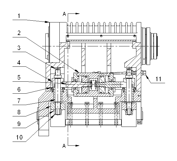
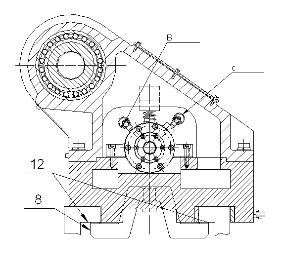
[0019] Such as figure 1 and figure 2 As shown, the hydraulic locking device of the tailstock of the horizontal CNC lathe of the present invention comprises a tailstock body 1, and a double piston rod oil cylinder 2 is installed in the lower space of the tailstock body 1, and the oil chamber in the piston rod oil cylinder 2 It is connected to the hydraulic control system of the machine tool through hydraulic oil pipes (11 in the figure is a straight-through joint). The double-piston rod cylinder 2 is equipped with two left and right piston rods 5, and the left and right piston rods 5 can respectively push the wedge 4 on the corresponding side under the hydraulic pressure of the cylinder to drive the pull rod 7 installed on the wedge 4 upward. Movement; the lower end of the pull rod 7 is equipped with a pressure plate 8, and the top is equipped with a compres...


PUM


Abstract

The invention relates to a hydraulic automatic locking device of a horizontal numerically controlled lathe tailstock. The hydraulic automatic locking device comprises a tailstock body, wherein a double-piston rod cylinder is arranged inside a lower space of the tailstock body; a left piston rod and a right piston rod arranged inside the double-piston rod cylinder can respectively push a wedge block at the corresponding side to drive a draw bar arranged on the wedge block to move upwards under the hydraulic effect of the cylinder; a pressure plate is arranged at the lower end of the draw bar; a compression spring is arranged at the top end; the pressure plate is driven to press a guide surface of a machine tool upwards when the draw bar moves upwards, so as to achieve locking of the tailstock, and the piston rods at two sides are recovered when the tailstock needs to be loosened, the compression spring can push the piston rod to move downwards; the pressure plate of pressing the guide surface of the machine tool is loosened; and an oil chamber inside the double-piston rod cylinder is connected with a hydraulic control system of the machine tool through a hydraulic oil pipe. The hydraulic automatic locking device is suitable for a horizontal lathe or a flat bed lathe, of which the tailstock needs to be locked; the production efficiency is improved; the labor intensity is reduced; stable and reliable locking is achieved, and the machining accuracy of a part is also guaranteed.

Description

technical field [0001] The invention relates to the technical field of auxiliary equipment for a horizontal numerically controlled lathe, in particular to a hydraulic automatic locking device for a tailstock of a horizontal numerically controlled lathe. Background technique [0002] In the prior art, the tailstock of horizontal CNC lathes is manually locked, that is, the tailstock is locked by tightening the screws on the pressure plate. Although such a locking structure is simple, the locking is unreliable, which increases the labor force of the workers. Labor intensity reduces production efficiency. At the same time, if the tailstock needs to be locked again after moving, the concentric deviation between the tailstock and the machine tool spindle will affect the processing accuracy of the parts due to the difference in locking force. Contents of the invention [0003] The purpose of the present invention is to overcome the above-mentioned defects in the prior art, provid...

Claims


Application Information

Patent Timeline
Patent Type & Authority Applications(China)
IPC IPC(8): B23B23/00
Inventor 王丽陈雁军祁卫中张居济马维新
Owner 宁夏新瑞长城机床有限公司
Why Eureka
Try Eureka