Cleaning device for roving and spinning unit yarn bin guide rail

A technology of cleaning device and joint yarn warehouse, which is applied in textiles and papermaking, can solve the problems of potential safety hazards, easy sticking of filter screens, and deterioration of working environment by flying dust, so as to achieve strong operational reliability, improve production efficiency, and ensure spinning The effect of yarn quality

Active Publication Date: 2013-03-27
CMT HICORP MACHINERY QINGDAO
View PDF6 Cites 1 Cited by
  • Summary
  • Abstract
  • Description
  • Claims
  • Application Information

AI Technical Summary

Problems solved by technology

[0003] During the use of the automatic thick and fine conveying system, with the prolongation of the use time, the high-speed operation of the equipment in the workshop brings a lot of flying flowers and dust, which will affect the product quality after remaining on the guide rail of the yarn storehouse. In addition, the accumulation of flying dust also deteriorates the working environment and affects production efficiency
At present, there are often two cleaning methods for these accumulated flowers: one is to use a ladder to climb for manual cleaning, which is not only time-consuming and laborious but also has potential safety hazards; Although this cleaning method saves manpower, the use effect is not very good, because this kind of itinerant cleaner generally only simply transforms the itinerant main body on the spinning equipment. Due to structural and formal constraints, this type of itinerant cleaner often has the disadvantages of small air volume, easy damage to the dragon belt, and especially the lack of fermentation such as the easy sticking of the filter screen when used on the entire thick and thin connection.

Method used


Image

  • Cleaning device for roving and spinning unit yarn bin guide rail
  • Cleaning device for roving and spinning unit yarn bin guide rail

Examples


Embodiment Construction

[0022] The present invention will be further described in detail below in conjunction with the accompanying drawings and specific embodiments, but the present invention is not limited to these embodiments.

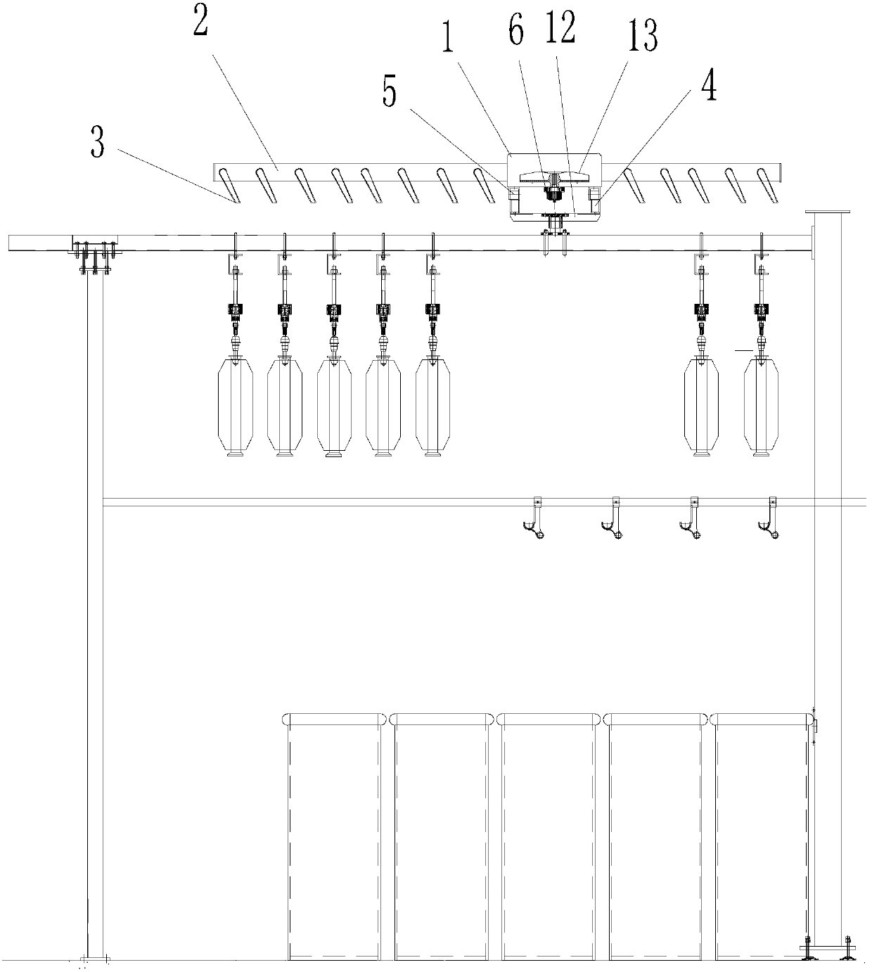
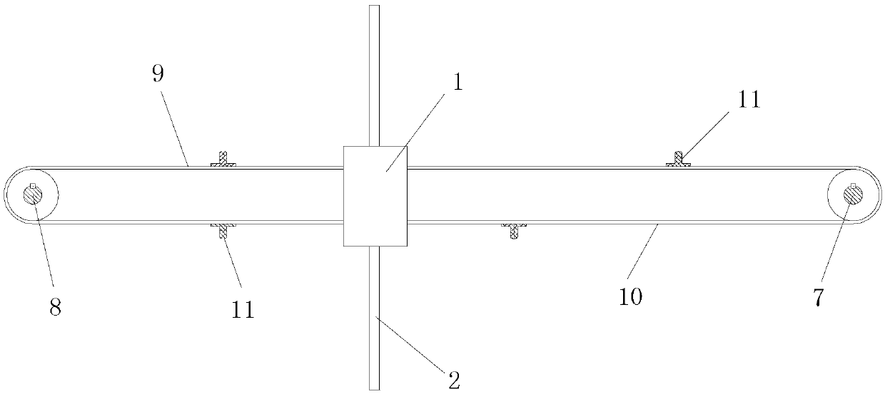
[0023] Figure 1 and figure 2 As shown, a thick and thin yarn storehouse guide rail cleaning device includes two parallel guide rails 4 installed on the yarn storehouse beam 12 and a blower mechanism that can slide along the guide rails 4. The blower mechanism includes a fan 1 and a The air ducts 2 on both sides of the fan 1, the bottom of the air duct 2 are evenly distributed with several oblique blowing nozzles 3, and the cleaning device for the guide rail of the thick and thin yarn warehouse also includes driving the blowing mechanism to slide along the guide rail 4 the drive mechanism.

[0024] The fan 1 includes an impeller 13, the bottom of the fan 1 is provided with first, second and third pulleys, the second pulley 6 is provided with a drive shaft, and the impeller...


PUM


Abstract

The invention discloses a cleaning device for a roving and spinning unit yarn bin guide rail. The cleaning device comprises two parallel guide rails which are installed on a yarn bin beam and a blowing mechanism which can slide along the guide rails, wherein the blowing mechanism comprises a fan and air pipes which are arranged on the two sides of the fan, and a plurality of inclined blowing nozzles are uniformly distributed on the bottom ends of the air pipes. The cleaning device for the roving and spinning unit yarn bin guide rail further comprises a drive mechanism which drive the blowing mechanism to slide along the guide rails. By the cleaning device, the labor and labor cost for cleaning are lowered, the production efficiency is increased, and the spinning quality is ensured; and the cleaning device has the advantages of simplicity in structure, convenience in installation and maintenance, low energy consumption, good cleaning effect and strong operation reliability.

Description

technical field [0001] The invention belongs to the field of textile machinery and equipment, and in particular relates to a cleaning device for guide rails of thick and thin yarn warehouses. Background technique [0002] Thick and thin combined conveying system is used to send the full bobbin roving falling from the roving frame to the full bobbin warehouse, and then send the full bobbin to the spinning frame after the spinning frame sends out a demand signal; send the empty bobbin used up by the spinning frame back to the empty bobbin After the roving frame sends a demand signal, the empty tube is sent to the roving frame for automatic doffing of the roving frame. As an important equipment to improve the technical level of my country's textile industry, thick and thin joints are an important way for my country's textile enterprises to change from labor-intensive to technology-intensive. With the continuous rise of labor costs in our country and the rapid transfer of labor...

Claims


Application Information

Patent Timeline
Patent Type & Authority Applications(China)
IPC IPC(8): D01H11/00
Inventor 王成吉崔桂华郭加阳李建霞周春娟尹怀秀赵天洁李凤翥
Owner CMT HICORP MACHINERY QINGDAO
Why Eureka
Try Eureka