
Numerical control rotating cam control fulcrum chute fuzzing mechanism

A technology of raising mechanism and cam control, which is applied in looms, textiles, textiles and papermaking, etc. It can solve the problems of complex transmission structure, unstable beating amount of sley, poor weaving precision, etc., and achieves convenient manufacturing and simple structure , high precision effect

Active Publication Date: 2013-03-27
JIANGSU YOUCHENG CNC TECH CO LTD
View PDF9 Cites 19 Cited by
  • Summary
  • Abstract
  • Description
  • Claims
  • Application Information

AI Technical Summary

Problems solved by technology

[0005] In order to overcome the disadvantages of the prior art, such as the complex transmission structure of the driving mechanism of the numerically controlled reed moving fluffing, the unstable beating-up amount of the sley, and the poor weaving precision, the present invention provides a simple structure, convenient production and stable sley beating-up, It has the functions of anti-error, anti-mistake and anti-overtravel, which can effectively ensure the precision of raising and weaving. The numerical control rotary cam controls the fulcrum chute raising mechanism

Method used


Image

  • Numerical control rotating cam control fulcrum chute fuzzing mechanism
  • Numerical control rotating cam control fulcrum chute fuzzing mechanism
  • Numerical control rotating cam control fulcrum chute fuzzing mechanism

Examples


Embodiment Construction

[0019] The present invention will be further described below in conjunction with drawings and embodiments.

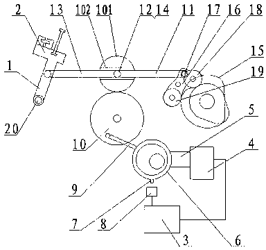
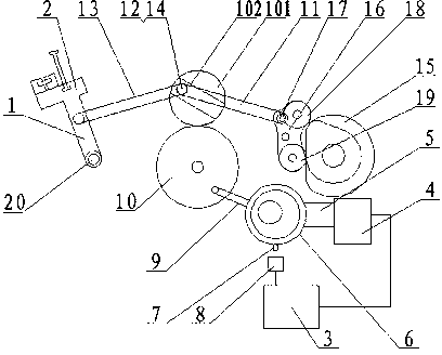
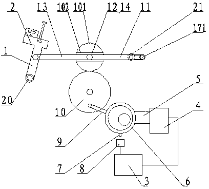
[0020] figure 1 In the first embodiment shown, the fluffing mechanism of the fulcrum chute controlled by the numerically controlled rotating cam includes an electric box 3, a numerically controlled motor 4, a reducer 5, an eccentric rotating cam 6, a signal convex 7, a signal sensor 8, a gear swing rod 9, and a lower gear 10 , Upper gear 101, chute 102, primary transmission link 11, hinge joint 12, secondary transmission link 13, slide block 14, conjugate cam group 15 and swing arm 16. The sley foot 1 swings and rotates with the sley fulcrum 20 as a fulcrum. Sley foot fulcrum 20, conjugate cam group 15, swing arm 16, upper gear 101, lower gear 102, eccentric rotating cam 6 are all installed on the loom frame in the form of bearing rolling connection, and the center distance is relatively fixed . The electric box 3 drives the eccentric rotating cam 6 sequentially thro...


PUM


Abstract

The invention relates to a numerical control rotating cam and control fulcrum chute fuzzing mechanism. The mechanism consists of a numerical control fuzzing drive mechanism, a fixed stroke reciprocating mechanism and a beating-up slay sword part which is under limiting control through a beating-up drive link and a numerical control fuzzing drive mechanism, wherein an electric box of the numerical control fuzzing drive mechanism drives an eccentric rotating cam through a numerical control motor and a reducing mechanism sequentially, and the eccentric rotating cam carries out drive control on a chute seat with a chute through a push-pull drive mechanism; and one end of the beating-up drive link is hinged with the fixed stroke reciprocating mechanism, the other end of the beating-up drive link is movably hinged to a slay sword, and the beating-up drive link is provided with a sliding block or a rotor which is limited in the chute and slides or rolls along the direction of the chute. A conjugate cam group or a crank changes a linear stroke of the beating-up drive link when the beating-up drive link moves towards the slay sword to a limiting point, so that the slay sword is stabilized, and beating up can be adjusted to beat weft yarns at different positions of a fell; and the mechanism is simple in structure, is convenient to manufacture and use and can be adjusted to meet different fuzz height requirements at any time.

Description

technical field [0001] The invention relates to a weft-beating and raising mechanism of a towel loom, in particular to a numerically controlled rotary cam-controlled fulcrum chute and live reed raising mechanism capable of weaving different wool heights. Background technique [0002] The raising mechanism of the traditional towel machine is divided into the raising of the reed and the raising of the cloth. The raising of the cloth adopts the control of the movable chest beam and the back beam of the loom so that the loom can be moved to complete the raising. The driving energy consumption is high, the yarn friction is large, and the strength requirements are high. It is not easy to synchronize the front and back, and the production efficiency is low; the reed moving fluffing controls the relative displacement of the beating point of the reed to control the height of each weft to achieve fluffing. It has the advantages of small line friction and high production efficiency. ...

Claims


Application Information

Patent Timeline
IPC IPC(8): D03D49/60
CPCD03D49/60
Inventor 王勇
Owner JIANGSU YOUCHENG CNC TECH CO LTD
Learn More