Energy-saving type vibration exciter for vibratory roller

A vibratory roller and vibration exciter technology, which is applied in the field of construction machinery, can solve the problems affecting the configuration power of the engine, the efficiency of the transmission system and the reliability of the whole machine, the unfavorable vibration starting and stopping of the vibrating machine, and the unstable compaction of the vibrating roller. , to achieve the effect of high promotion and application value, good economic benefits and simple structure

Inactive Publication Date: 2013-03-27
CHANGAN UNIV
View PDF7 Cites 11 Cited by
  • Summary
  • Abstract
  • Description
  • Claims
  • Application Information

AI Technical Summary

Problems solved by technology

This kind of structure has a large vibration mass, which leads to a large moment of inertia. The instantaneous power of the vibratory roller is too large during the vibration start/stop process, and the engine speed drops seriously, which affects the engine configuration power, transmission system efficiency and overall machine reliability.
For the operation situation, it will make the compaction of the vibratory roller unstable, affect the compaction quality, and the economy is poor
T

Method used


Image

  • Energy-saving type vibration exciter for vibratory roller
  • Energy-saving type vibration exciter for vibratory roller
  • Energy-saving type vibration exciter for vibratory roller

Examples


Embodiment 1

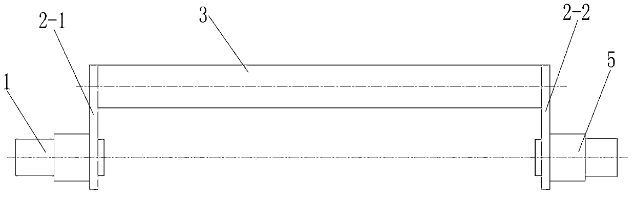
[0030] Such as figure 1 As shown, the present invention includes a vibrator body, and the vibrator body includes a first transmission shaft 1 and a second transmission shaft 5 arranged at intervals, and the first transmission shaft 1 is fixedly connected with a first shaft protruding upward. The connecting crank 2-1, the second transmission shaft 5 is fixedly connected with the second connecting crank 2-2 extending upwards and having the same length as the first connecting crank 2-1, the first connecting crank 2- 1 and the second connecting crank 2-2 are fixedly connected with a fixed bar 3 for generating an exciting force, and the fixed bar 3 is parallel to the first transmission shaft 1 and the second transmission shaft 5 .

[0031] In this embodiment, the first connecting crank 2-1 is welded to the first transmission shaft 1, the second connecting crank 2-2 is welded to the second transmission shaft 5, and the fixed bar 3 One end is welded with the first connecting crank 2...

Embodiment 2

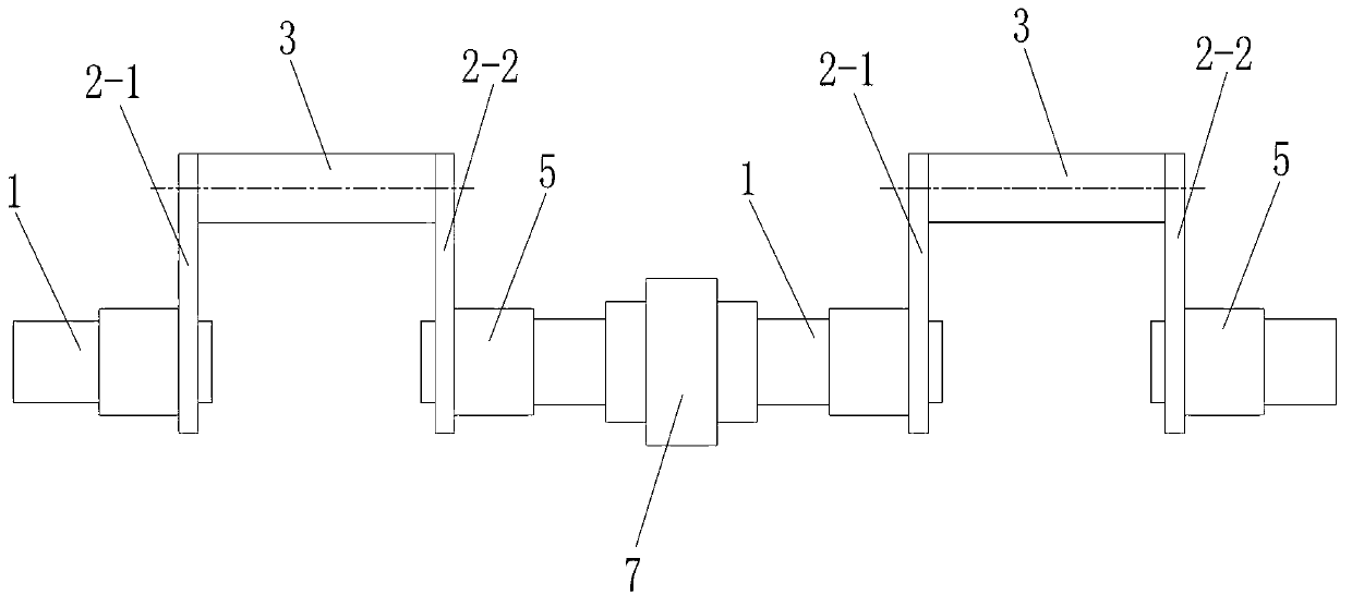
[0034] Such as figure 2 As shown, the difference between this embodiment and Embodiment 1 is that the number of the exciter bodies is two, and the two exciter bodies are connected through a coupling 7 . All the other structures are the same as in Example 1.

[0035] When the exciter is specifically processed and manufactured, the length of the fixed bar 3 is relatively short, and the overall length of the exciter body is relatively short. Two such exciter bodies are required to form an exciter for a vibratory road roller. The working principle and embodiment 1 is the same.

Embodiment 3

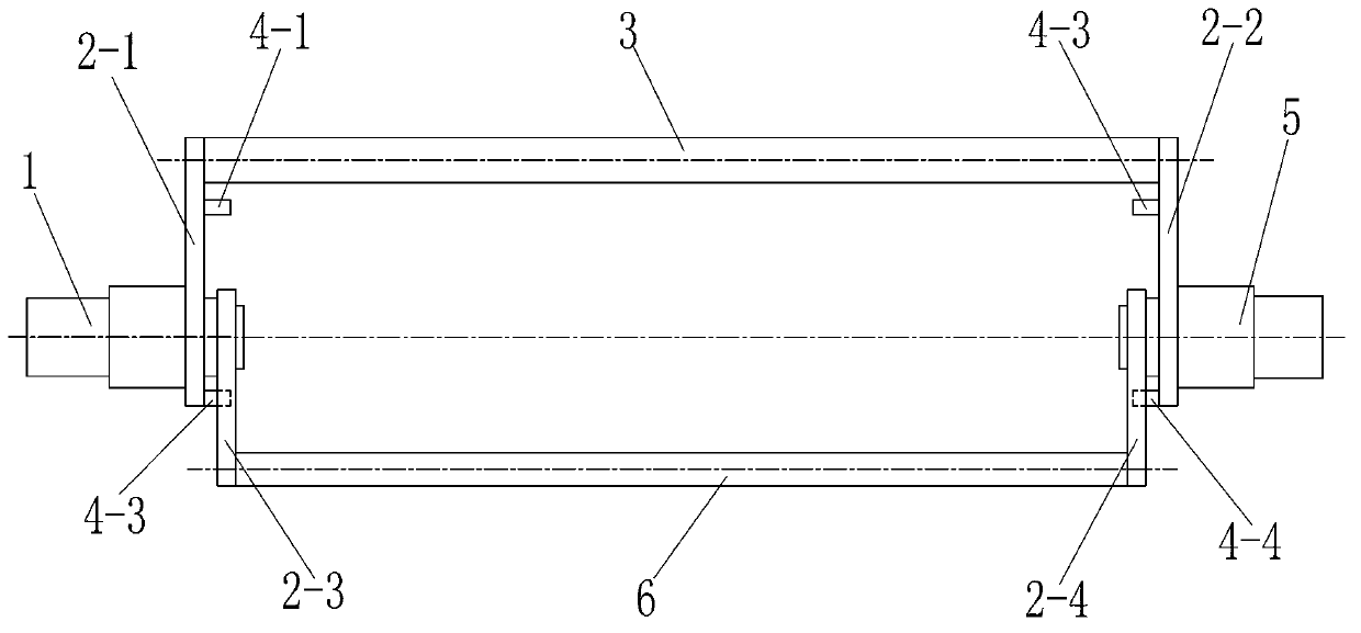
[0037] Such as image 3 As shown, the difference between this embodiment and Embodiment 1 is that a section of the first transmission shaft 1 located inside the first connecting crank 2-1 is rotatably connected with a third connecting crank 2 protruding downward through a first bearing. -3, a section of the second transmission shaft 5 located inside the third connecting crank 2-3 is rotatably connected to a fourth connecting part extending downwards and having the same length as the third connecting crank 2-3 through a second bearing The crank 2-4, the third connecting crank 2-3 and the fourth connecting crank 2-4 are fixedly connected with a movable bar 6 for cooperating with the fixed bar 3 to adjust the amplitude of the vibratory road roller. The inner side of a connecting crank 2-1 is provided with a first upper stop pin 4-1 above the first transmission shaft 1 and a first lower stop pin 4-2 below the first transmission shaft 1, the The inner side of the second connecting...


PUM


Abstract

The invention discloses an energy-saving type vibration exciter for a vibratory roller. The energy-saving type vibration exciter for the vibratory roller comprises first drive shafts and second drive shafts, and the first drive shafts and the second drive shafts are arranged in an interval mode. First connecting cranks extending upward are fixedly arranged on the first drive shafts, second connecting cranks extending upward are fixedly arranged on the second drive shafts, the first connecting cranks and the second connecting cranks are of the same length; fixing rods which are used for producing exciting force are fixedly arranged between the first connecting cranks and the second connecting cranks; and the fixing rods are parallel with the first drive shafts and the second drive shafts. The energy-saving type vibration exciter for the vibratory roller has the advantages of being simple in structure, reasonable in design, convenient to process, high in operational reliability, low in carrying out, good in operational stability, having long working life, being capable of reducing the energy in the vibration starting and vibration stop of the vibratory roller effectively, good in saving energy, good in practical applicability and high in popularization and application values.

Description

technical field [0001] The invention belongs to the technical field of construction machinery, in particular to an energy-saving vibrator for a vibratory road roller. Background technique [0002] Existing exciters for vibratory road rollers generate excitation force through an eccentric mass installed on the vibrating shaft, and change the angle between the fixed eccentric mass and the movable eccentric mass through forward and reverse rotation to adjust the amplitude. This kind of structure has a large vibration mass, resulting in a large moment of inertia. The instantaneous power of the vibratory roller is too large during the vibration start / stop process, and the engine slows down seriously, which affects the engine configuration power, transmission system efficiency and overall machine reliability. For the operation situation, it will make the compaction of the vibratory roller unstable, affect the compaction quality, and the economy is poor. The exciters used in other...

Claims


Application Information

Patent Timeline
IPC IPC(8): E01C19/28
Inventor 张志峰孔鲜宁徐会敢
Owner CHANGAN UNIV
Why Eureka
Try Eureka