Diaphragm plate type idle speed control valve

A technology of idle speed control valve and diaphragm plate, which is applied in engine control, machine/engine, mechanical equipment, etc., can solve the problems of unstable idle speed, bearing slippage, aging of rotating core, unstable idle speed condition, etc., to increase riding comfort. performance, prolonging service life

Active Publication Date: 2013-03-27
昌辉汽车电器(黄山)股份公司
View PDF9 Cites 2 Cited by
  • Summary
  • Abstract
  • Description
  • Claims
  • Application Information

AI Technical Summary

Problems solved by technology

However, this structure cannot accurately adjust the opening degree of the valve. The opening degree of the valve is only controlled by the magnitude of the electrical signal input by the coil, and the actual change of the air pressure between the inlet and outlet of the valve cannot be used to achieve real-time opening of the valve. Adjustment, resulting in unstable idling, which reduces the ride comfort of the car
[0004] The invention patent with the Chinese patent publication number CN102619630A discloses a stepper motor type idle speed control valve, which solves the problems of slipping of the bearing, aging of the rotating core and virtual welding between the coil and the pin
[0005] Although the above-mentioned patent provides a structure of a stepping motor type idle speed control valve, the opening degree of the valve cannot be precisely adjusted by this structure, and the opening degree of the valve cannot be adjusted by the actual change of the air pressure between the air inlet and outlet of the valve. When it is adjusted in real time, the idling condition will still be unstable, and the comfort of the car will still be affected

Method used


Image

  • Diaphragm plate type idle speed control valve

Examples


Embodiment Construction

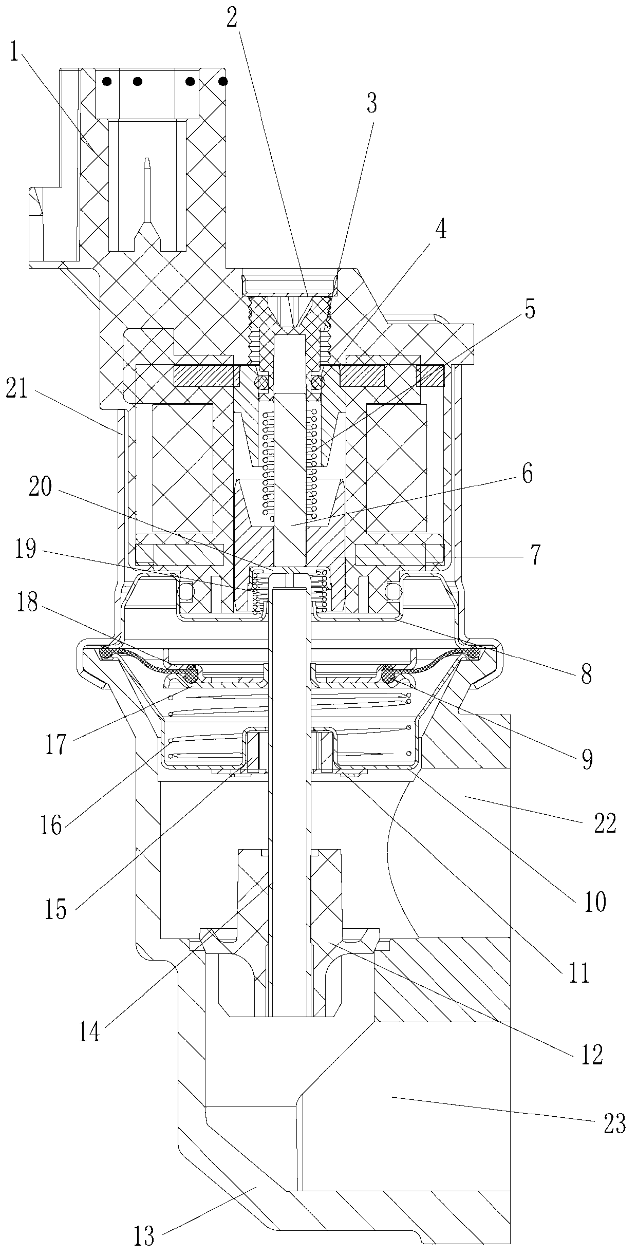
[0019] Please also refer to figure 1 , as shown in the figure, a diaphragm plate type idle speed control valve includes a valve body, the valve body includes a coil package assembly, and a valve seat 13 installed in cooperation with the coil package assembly. The valve seat 13 is provided with upper and lower settings The air inlet 22 and the air outlet 23, the coil package assembly further includes a coil package assembly 1 cooperating with the installation, a sleeve 21 riveted with the coil package assembly 1, a piston assembly, a third compression spring 19 and The upper cover plate 8, the piston assembly, the third compression spring 19 and the upper cover plate 8 are sequentially installed in the coil package assembly 1, and the piston assembly further includes a valve stem 6, a piston 7 cooperating with the valve stem 6, and a press-in The sealing cover 20 in the piston 7, the valve body further includes a diaphragm plate assembly, the diaphragm plate assembly includes a...


PUM


Abstract

The invention discloses a diaphragm plate type idle speed control valve, comprising a valve body, wherein the valve body comprises a coil bag assembly component, and a valve base mounted in match with the coil bag assembly component; the coil bag assembly component comprises a coil bag assembly mounted in a matched manner, a sleeve, a piston assembly, a third pressure spring and an upper cover plate; the sleeve, the piston assembly, the third pressure spring and the upper cover plate are integrally riveted with the coil bag assembly; the valve body comprises a diaphragm plate component; the diaphragm plate component comprises a diaphragm plate assembly, a lower cover plate assembly, a second pressure spring and a transmission rod assembly; the diaphragm plate assembly and the lower cover plate assembly are mounted in the matched manner; the second pressure spring is arranged between the diaphragm plate assembly and the lower cover plate assembly; the diaphragm plate assembly comprises a lower pressing plate, a diaphragm plate and an upper pressing plate, which are mounted in the matched manner; and a vacuum chamber is formed between the diaphragm plate assembly and the coil bag assembly component. The diaphragm plate type idle speed control valve provided by the invention can accurately control the flow of air entering an engine according to vacuum variation caused by variation of a working condition of an idle speed of the engine, so that the idle speed of an automobile is table, the service life of the engine is prolonged, and the riding comfort degree of the automobile can be improved.

Description

technical field [0001] The invention relates to an automobile idle speed control system, in particular to a diaphragm plate type idle speed control valve. Background technique [0002] The idle speed control valve is powered by the ignition switch, as long as the ignition switch is turned to the ON position, the idle speed control valve is powered on, and the engine computer controls its circuit to ground. This valve is used to adjust the engine idle speed when the engine's operating parameters deviate from normal values. Idle speed is adjusted by controlling the amount of air bypassing the throttle body. After the engine is started, the idle speed control valve is opened for a period of time to increase the intake air, which increases the engine idle speed by about 150r / min-300r / min. When the engine coolant temperature is low, the idle speed control valve opens to obtain a proper fast idle speed. The engine computer controls the position of the plunger of the idle speed ...

Claims


Application Information

Patent Timeline
Patent Type & Authority Applications(China)
IPC IPC(8): F02D9/08F02D17/04
Inventor 王进丁王正成朱排进李宏志
Owner 昌辉汽车电器(黄山)股份公司
Why Eureka
Try Eureka