
Capacitive ultra-large strain sensor

A strain sensor and capacitive technology, applied in the direction of electric/magnetic solid deformation measurement, electromagnetic measurement devices, etc., can solve the problems of unable to realize the design of curved surface measurement structure, unable to meet the needs of large strain measurement, etc., to achieve good application prospects, high resolution High efficiency, good linearity and repeatability

Inactive Publication Date: 2015-08-19
NO 49 INST CHINESE ELECTRONICS SCI & TECH GRP
View PDF3 Cites 0 Cited by
  • Summary
  • Abstract
  • Description
  • Claims
  • Application Information

AI Technical Summary

Problems solved by technology

[0003] The technical problem to be solved in the present invention is that there are certain restrictions on the measurement of super large strain in the prior art, which cannot meet the requirements of large strain measurement, and at the same time, the problem that the prior art cannot realize curved surface measurement and realize structural design in a very small size, In order to overcome the above defects, it is necessary to develop a sensor that can realize ultra-large strain detection, which can be miniaturized and can measure curved surfaces. The size of the strain amount, the strain ε of the present invention is above 0.3, can effectively solve the problem of super large strain measurement, use the pull-type strain-sensing structure endpoint installation technology to realize the surface measurement, and adopt the double capacitance sensitivity design to realize the structural design in a very small space , to increase the sensitivity of the sensor

Method used


Image

  • Capacitive ultra-large strain sensor
  • Capacitive ultra-large strain sensor
  • Capacitive ultra-large strain sensor

Examples


Embodiment Construction

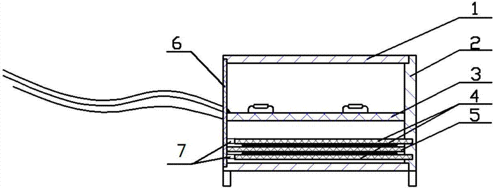
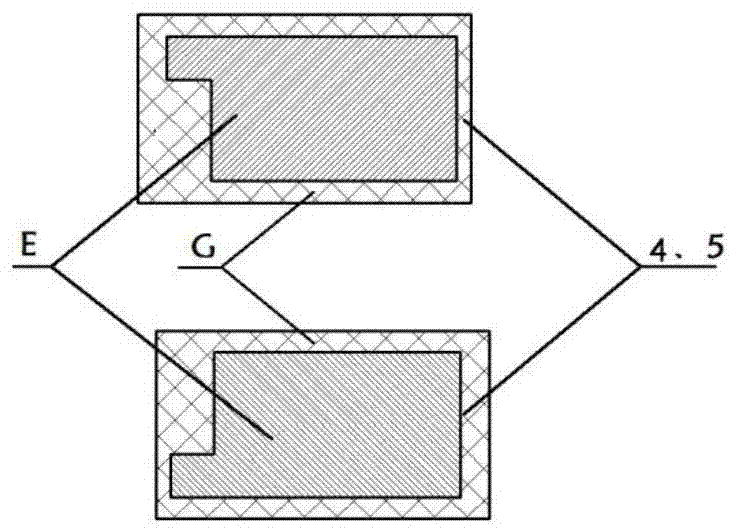
[0014] refer to figure 1 , represents the structure diagram of the capacitive ultra-large strain sensor involved in the present invention, and its shape is a rectangular frame structure, which consists of a housing 1, a drag frame 2, a circuit assembly board 3, a capacitive moving plate 4, a capacitive fixed plate 5, The lead plate is composed of 6, and the structural diagram of the capacitive ultra-large strain sensor is shown in figure 1 shown. The circuit component board 3 is first fixed on the lead plate 6 by welding and then glued and fixed on the inner wall of the casing 1, the capacitive plate 4 is fixed with the drag frame 2 with glue, and the drag frame 2 is fixed with the casing 1. The slideway 7 forms a sliding connection. The capacitor fixed plate 5 is fixed on the lead plate 6 by welding, and then secondly cured by applying glue around it, and finally the lead plate 6 and the shell 1 are bonded and fixed. When the sensor is installed, one end of the housing 1 a...


PUM


Abstract

The invention relates to a capacitor type superhigh strain sensor and belongs to the field of electronic components. The capacitor type superhigh strain sensor comprises a top outer casing, a lateral drawing frame , a middle circuit component, lower capacitor movable electrode plates, a lower capacitor fixed electrode plate, slideways and a lead plate, wherein the slideways and the lead plate are arranged on the outer casing. The circuit component in the middle of the superhigh strain sensor is fixed on the lead plate by welding and fixed on the inner wall of the outer casing by adhering, the capacitor movable electrode plates and the capacitor fixed electrode plate arranged on the lower portion are fixed by adhesives, and the drawing frame is slidably connected with the slideways of the outer casing. The capacitor fixed electrode plate between the two capacitor movable electrode plates is fixed on the lead plate by welding, and the lead plate is fixedly connected with the outer casing. Superhigh strain measurement is realized in a capacitor variable-area way, measuring of curved-surface objects to be measured is realized by a drawing type sensing structure, and structural design in a narrow space is realized by bi-capacitor sensitization. The capacitor type superhigh strain sensor has the advantages of miniaturization, high accuracy and definition rate and the like.

Description

technical field [0001] The invention belongs to the field of electronic devices, in particular to a capacitive ultra-large strain sensor. Background technique [0002] The strain refers to the amount of deformation per unit length of an object, and its expression is ε=ΔL / L. A capacitive ultra-large strain sensor uses displacement measurement to detect the strain of the structure under test. Strain detection is the most effective method to eliminate structural safety hazards and improve the life of the measured object. It has attracted the attention of experts and scholars at home and abroad. The strain information can be used to invert the external load of the structure, evaluate the structural safety and locate the damage. The size of the sensor design can affect the corresponding variables. How to design the structure in a given extremely narrow space and realize the small-sized miniaturized sensor has always been an important topic in the field of sensor design at home an...

Claims


Application Information

Patent Timeline
Patent Type & Authority Patents(China)
IPC IPC(8): G01B7/16
Inventor 李起栋段成丽宫占江魏鸿雁沈广楠张美玉史鑫孙立凯陈丽洁
Owner NO 49 INST CHINESE ELECTRONICS SCI & TECH GRP
Learn More