
Direct detection system for surface-shape errors in full-aperture optical aspheric surfaces

A surface shape error and detection system technology, applied in the direction of optical devices, measuring devices, instruments, etc., can solve the problems of long measurement period, high cost, large amount of data, etc., achieve shortened detection preparation cycle, reduce detection cost, and measure wide range of effects

Inactive Publication Date: 2015-06-03
BEIJING INSTITUTE OF TECHNOLOGYGY
View PDF2 Cites 0 Cited by
  • Summary
  • Abstract
  • Description
  • Claims
  • Application Information

AI Technical Summary

Problems solved by technology

[0004] The purpose of the present invention is to solve the problems of difficult manufacturing of auxiliary optical elements (large-diameter high-precision mirrors, compensators), long measurement period, high cost, sensitive assembly error and large amount of data in the existing aspheric surface detection technology. Propose a full-aperture optical aspheric direct detection system

Method used


Image

  • Direct detection system for surface-shape errors in full-aperture optical aspheric surfaces
  • Direct detection system for surface-shape errors in full-aperture optical aspheric surfaces
  • Direct detection system for surface-shape errors in full-aperture optical aspheric surfaces

Examples


Embodiment Construction

[0030] The present invention will be described in detail below in conjunction with the accompanying drawings and specific embodiments.

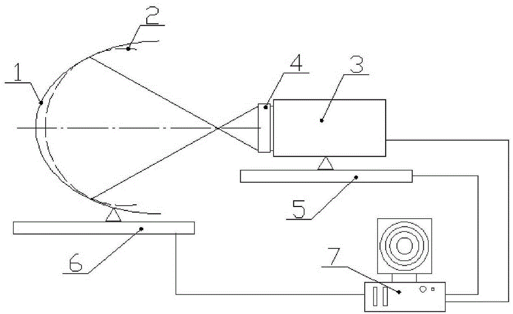
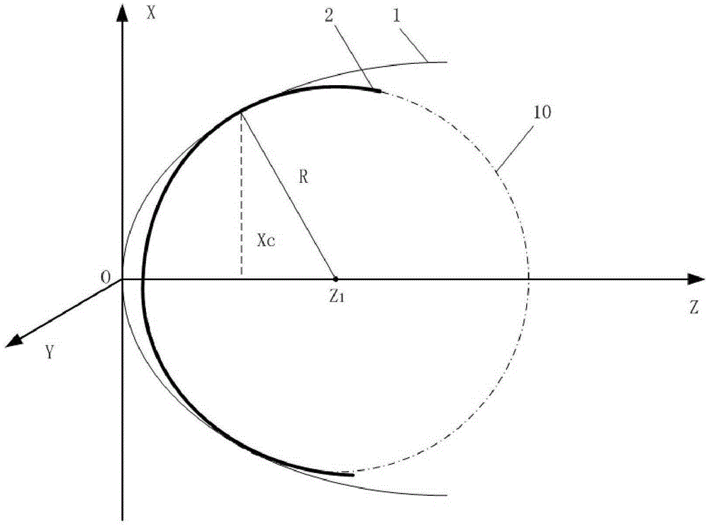
[0031] Such as figure 1 As shown, the device of a full-aperture optical aspheric surface error direct detection system of the present invention includes an interferometer 3, a standard spherical transmission lens 4, a one-dimensional electronically controlled translation stage 5, a five-dimensional precision electronically controlled platform 6, and a computer system 7 composition. The standard spherical transmission lens 4 is fixed in front of the interferometer 3, and the optical axes of the two are on the same straight line; the measured optical aspheric surface 1 is fixed on the five-dimensional precision electronic control platform 6, and the five-dimensional precision electronic control platform is adjusted by the computer system 7. The control platform 6 makes the optical axes of the measured optical aspheric surface 1, the standard s...


PUM


Abstract

The invention relates to a direct detection system for surface-shape errors in full-aperture optical aspheric surfaces. The system comprises an interferometer, a standard spherical transmitting lens, a one-dimensional motorized translation stage, a five-dimensional precision motorized stage and a numerical control system. The position of the interferometer and the position of an aspheric surface to be detected are adjusted through the one-dimensional motorized translation stage and the five-dimensional precision motorized stage, the spherical wave generated by the interferometer is matched with a certain inscribed circle of the detected aspheric surface, and wave path difference between the detected aspheric surface and a comparison spherical surface is measured with the interferometer. Feature points of the wave path difference are extracted and subjected to circle fitting so as to obtain optimal matching point position, so that a comparison spherical rise equation is calculated. Finally, the wave path difference is subtracted by a theoretical rise difference between the aspheric surface and the comparison spherical surface so as to obtain the surface-shape error of the aspheric surface detected. A method for detecting surface-shape errors of aspheric surfaces is high in precision and efficiency and economical with no need of auxiliary lenses and compensators.

Description

technical field [0001] The invention relates to an optical aspheric surface detection system, in particular to a full-aperture aspheric surface shape error direct detection system, which belongs to the technical field of advanced optical detection. Background technique [0002] With the continuous development of advanced optical manufacturing and detection technology, the precision optical system with aspheric surface as the key component has been more and more deeply applied in the fields of astronomy, space optics and military affairs. Its remarkable advantages are: adding aspheric optical elements in the design of the optical system can not only increase the degree of freedom of the optical designer, but also can more effectively correct aberrations, improve image quality, expand the field of view, increase the working distance, and one or A few aspherical mirrors can replace more spherical mirrors, thereby simplifying the structure of the optical system, reducing cost an...

Claims


Application Information

Patent Timeline
Patent Type & Authority Patents(China)
IPC IPC(8): G01B11/24
Inventor 程灏波文永富
Owner BEIJING INSTITUTE OF TECHNOLOGYGY
Learn More