Field sampling device and sampling method of filling slurry

A technology of on-site sampling and filling slurry, applied in sampling devices and other directions, can solve problems such as insufficient research on flow characteristics, settling characteristics and strength distribution characteristics, restricting the settling characteristics of filling aggregates, binder distribution characteristics, and difficulty in being representative. , to achieve the effect of optimizing the stope structure size, facilitating on-site processing and production, and scientific sampling methods

Inactive Publication Date: 2013-03-27
UNIV OF SCI & TECH BEIJING
View PDF4 Cites 5 Cited by
  • Summary
  • Abstract
  • Description
  • Claims
  • Application Information

AI Technical Summary

Problems solved by technology

At the same time, due to the influence of drainage water and pipe brushing water, the samples taken at the feeding nozzle cannot reflect the real situation of the stope; (2) The filling slurry will segregate in the underground stope, and the gelation of the filling slurry in different depth ranges The content, concentration, and composition of aggregate particles all have great changes, and these factors are the key to determining the strength of the filling body. Therefore, method 2 is affected by various factors such as the dilution of the upper low-concentration filling slurry during the sampling process. (3) Both of the above two methods are difficult to obtain actual filling slurry samples at different depths and positions in the filling stope, which greatly restricts the research on the filling slurry in the stope. The settlement characteristics of the inner filling aggregate and the distribution characteristics of the cement are also an important reason for the lack of research on the flow characteristics, settlement characteristics and strength distribution characteristics of the filling slurry in the underground stope.

Method used


Image

  • Field sampling device and sampling method of filling slurry
  • Field sampling device and sampling method of filling slurry
  • Field sampling device and sampling method of filling slurry

Examples


Embodiment Construction

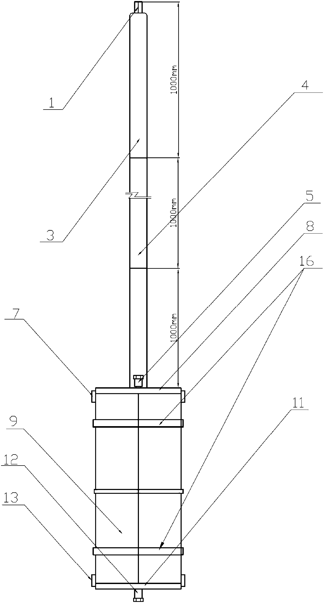
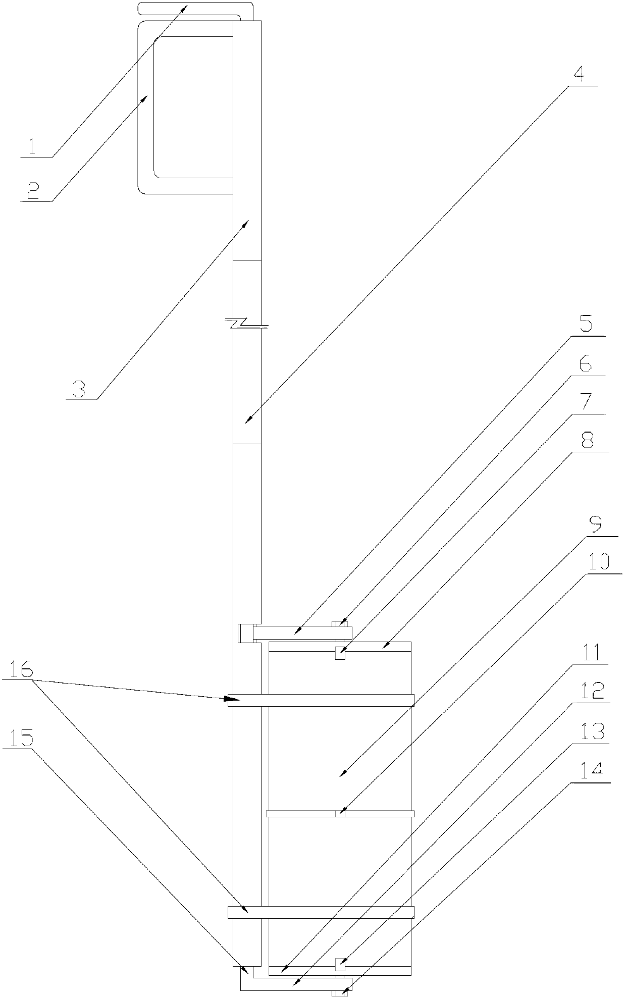
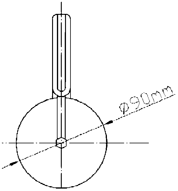
[0038] The on-site sampling device for filling slurry provided by the present invention includes a slurry cylinder control unit and a slurry cylinder, see figure 1 - As shown in Figure 7, the purpose of the slurry cylinder control unit is to place the slurry cylinder to a predetermined sampling position, and to control the opening and closing of the upper baffle (8) and the lower baffle (11) of the slurry cylinder for flexible sampling The main function of the slurry tank is to fill the slurry. There are various connecting components in the slurry tank to fix and connect the various parts of the slurry tank to prevent the slurry from flowing out.

[0039] Slurry tank control unit

[0040] Such as Figure 1-3As shown, the slurry cylinder control unit includes a sampling rod, an upper cross rod (5), and a lower cross rod (12), wherein the sampling rod is composed of a main rod (3) and a control rod (15); in the main rod (3) 1. The top of the control rod (15) can also be prov...


PUM

PropertyMeasurementUnit
diameteraaaaaaaaaa
lengthaaaaaaaaaa

Abstract

The invention provides a field sampling device and a use method of filling slurry. The sampling device comprises a slurry cylinder control unit and a slurry cylinder, wherein the slurry cylinder control unit comprises a sampling rod, an upper transverse rod 5, and a lower transverse rod 12, and a control rod 15 is axially inserted into a main rod 3; the slurry cylinder comprises a slurry cylinder upper baffle 8, a slurry cylinder pipe 9 and a slurry cylinder lower baffle 11; and one end of the upper / lower transverse rod is fixedly connected with the control rod, and the other end of the upper / lower transverse rod is detachably connected with the slurry cylinder upper / lower baffle 8. According to the field sampling device and a sampling method of the filling slurry, the field sampling of the filling slurry is realized by driving the opening and the closing of the upper baffle 8 and the lower baffle 11 by the control rod of the slurry cylinder control unit; and the slurry at a fixed point can be precisely collected, the sampling can not be influenced by low-concentration filling slurry at the upper part of a collecting field in the rising processes of sampled samples, and the property of the filling slurry in the collecting field can be accurately acquired.

Description

technical field [0001] The invention relates to an on-site sampling device for filling slurry and a method thereof, which can be applied to sampling filling slurry in goafs of underground mines adopting a filling mining method. Background technique [0002] The filling mining method has obvious advantages in fully recovering mineral resources, controlling deep mining ground pressure activities and improving environmental protection, and has achieved remarkable results. Therefore, it has attracted widespread attention in the mining industry. More and more widely used, 45% of large and medium-sized non-ferrous metal mines and 37% of gold mines in my country's underground mines use the filling method. [0003] This kind of mining method generally establishes a filling mixing station on the surface, prepares cement, sand, tailings, etc. according to a certain proportion into a fluid filling slurry, and passes through surface pipelines, drill holes connecting the surface and under...

Claims


Application Information

Patent Timeline
Patent Type & Authority Applications(China)
IPC IPC(8): G01N1/10
Inventor 韩斌仪海豹吴爱祥韩思愉王贻明王洪江尹升华李佳梦沈显岭
Owner UNIV OF SCI & TECH BEIJING
Why Eureka
Try Eureka