Membrane surface resistance test method of lithium ion battery

A lithium-ion battery and testing method technology, applied in the field of lithium-ion battery diaphragm surface resistance testing, can solve the problems of affecting the accuracy of test results, many testing procedures, and high testing costs, so as to achieve intuitive test results, ensure accuracy, and ensure accurate test results. sexual effect

Active Publication Date: 2013-03-27
SHENZHEN SENIOR TECH MATERIAL
View PDF4 Cites 12 Cited by
  • Summary
  • Abstract
  • Description
  • Claims
  • Application Information

AI Technical Summary

Problems solved by technology

In the prior art, the method of testing the conductivity is basically used to evaluate the performance of the diaphragm. There is a large error between the test value obtained by this method and the real value. The reason is that when the conductivity test is performed on a thinner diaphragm, there is It is difficult to control the distance accurately, and the roughness of the contact surface between the electrode plate and the diaphragm also affects the accuracy of the test results
Therefore, when using the conductivity method to evaluate the performance of the diaphragm, it is necessary to control the distance between the two electrodes, as well as the distance between the electrode plates and the roughness of the contact surface of the diaphragm, which requires a lot of equipment and testing procedures, resulting in high cost of testing
At present, the surface resistance of lithium-ion battery separators is mostly tested with general-purpose testing equipment for surface resistance, and there are few methods specifically for testing the surface resistance of lithium-ion battery separators. The existing methods for testing the surface resistance of lithium-ion battery separators are complex and The operation is inconvenient, the test cost is high, and the error of the test result is also large, and some even have potential safety hazards

Method used


Image

  • Membrane surface resistance test method of lithium ion battery
  • Membrane surface resistance test method of lithium ion battery
  • Membrane surface resistance test method of lithium ion battery

Examples


Embodiment Construction

[0026] In order to make the object, technical solution and advantages of the present invention clearer, the present invention will be further described in detail below in conjunction with the accompanying drawings and embodiments. It should be understood that the specific embodiments described here are only used to explain the present invention, not to limit the present invention.

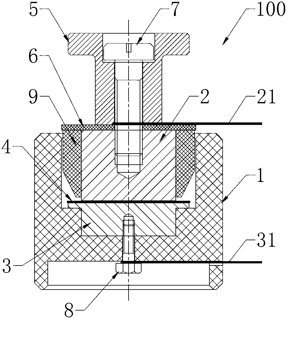
[0027] The embodiment of the present invention provides a method for testing the surface resistance of a lithium-ion battery separator, the method comprising the following steps:

[0028] Punching the diaphragm to be tested into a sample sheet of a suitable size, and soaking the diaphragm to be tested with lithium ion electrolyte in a sealed environment;

[0029] After the diaphragm to be tested is fully infiltrated, it is clamped between the two electrode plates, and the two electrode plates are placed in the lithium ion electrolyte, wherein the two electrode plates are connected to the testable r...


PUM


Abstract

The invention provides a membrane surface resistance test method of a lithium ion battery. The method comprises the following steps: stamping a membrane into a sample piece and soaking in lithium ion electrolyte, clamping between two electrode plates after soaking and placing in the electrolyte, connecting the electrode plates with an electrochemical work station, and polishing the clamping surface; drawing a resistance value on a coordinate system of membrane level number and resistance value; overlapping membranes for testing successively according to the above steps; and calculating a discrete point curve slope, wherein the membrane surface resistance is the slope multiplied by the area of the clamping surface. At least two times of testing is carried out on the same kind of membrane, and the difference value of the membrane surface resistances obtained in any two times is not more than 5%, and finally the membrane surface resistances obtained in each time of testing are averaged, wherein the average value is decided to be the final surface resistance value of the membrane. Before testing, the membrane to be tested is soaked with lithium ion electrolyte for two hours under a sealing environment. The method provided by the invention can conveniently and accurately measure the surface resistance of the membrane.

Description

technical field [0001] The invention relates to the technical field of battery testing, in particular to a method for testing the surface resistance of a lithium-ion battery diaphragm. Background technique [0002] A lithium-ion battery consists of a positive electrode, a negative electrode, a separator, and an electrolyte. The diaphragm is placed between the positive and negative electrodes to prevent direct contact between the positive and negative electrodes. It only allows ions to pass through, and electrons cannot pass through the diaphragm. The pore structure and ion passage rate of the separator directly affect the overall performance of the lithium-ion battery. [0003] There are a large number of zigzagging micropores in the separator. Ions move through the micropores and move between the positive and negative electrodes to form the internal conductive circuit of the battery, while electrons migrate between the positive and negative electrodes through the external ...

Claims


Application Information

Patent Timeline
IPC IPC(8): G01R27/02
Inventor 陈秀峰陈良何方波王今刚
Owner SHENZHEN SENIOR TECH MATERIAL
Why Eureka
Try Eureka