Super-resolution differential interference phase contrast microscopic imaging system and microscopic imaging method

A differential interference and phase-contrast imaging technology, applied in microscopes, instruments, optics, etc., can solve the problems of low imaging contrast, inapplicability, phototoxicity effects, etc., and achieve the effect of high imaging contrast

Active Publication Date: 2013-03-27
HUAZHONG UNIV OF SCI & TECH
View PDF3 Cites 28 Cited by
  • Summary
  • Abstract
  • Description
  • Claims
  • Application Information

AI Technical Summary

Problems solved by technology

[0003] The first is an imaging system that applies structured light illumination to fluorescence microscopy imaging. It has good contrast, but its main problems are as follows: 1) To perform fluorescence imaging, it is necessary to perform fluorescence on the observed sample. 2) In the above sample preparation process, substances such as dyes or fluorophores need to be added to the sample, so some side effects may be introduced, such as photobleaching effect and phototoxicity effect

Method used


Image

  • Super-resolution differential interference phase contrast microscopic imaging system and microscopic imaging method
  • Super-resolution differential interference phase contrast microscopic imaging system and microscopic imaging method
  • Super-resolution differential interference phase contrast microscopic imaging system and microscopic imaging method

Examples


Embodiment 1

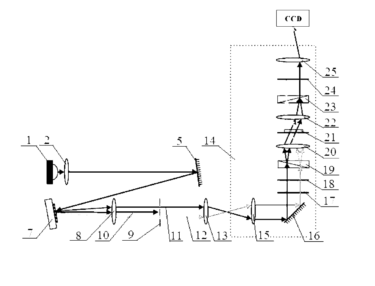
[0036] See attached figure 1 The super-resolution differential interference phase contrast microscopic imaging system provided by Embodiment 1 of the present invention includes a microscope 14 comprising a differential interference phase contrast imaging module, and the microscope 14 comprising a differential interference phase contrast imaging module includes a fifth lens 15, a fifth lens, and II mirror 16, polarizer 17, Wave plate 18, first prism 19, condenser lens 20, sample stage 21, objective lens 22, second prism 23, analysis piece 24, tube lens 25. The imaging system also includes a light source 1, a first lens 2, a first mirror 5, a spatial light modulator 7, a third lens 8, a light blocking plate 9, a fourth lens 13 and a CCD. The incident angle of the spatial light modulator 7 is <10°, the spatial light modulator 7 has three phases in each direction, and the light baffle plate 9 is used to block the 0-order light 10 and allow the +1-order light 11 and the -1-order ...

Embodiment 2

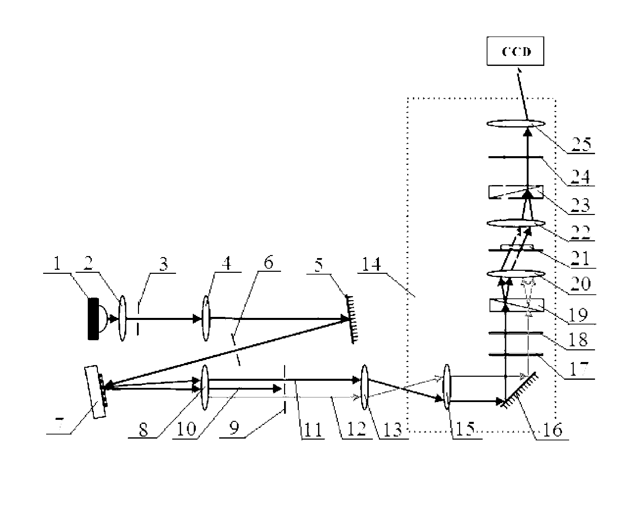
[0038] See attached figure 2 The difference between the super-resolution differential interference phase contrast microscopic imaging system provided by the second embodiment of the present invention and the super-resolution differential interference phase contrast microscopic imaging system provided by the first embodiment of the present invention is that the first lens 2 and the first reflection A first stop 3 and a second lens 4 are arranged in sequence between the mirrors 5 , and a second stop 6 is also arranged between the first reflecting mirror 5 and the spatial light modulator 7 . The light emitted by the light source 1 sequentially passes through the first lens 2, the first stop 3, the second lens 4, the first reflector 5, the second stop 6, the spatial light modulator 7, the third lens 8, and the light baffle plate 9 After the IV lens 13 passes through the microscope 14 including the differential interference phase contrast imaging module, the image is received by t...


PUM


Abstract

The invention discloses a super-resolution differential interference phase contrast microscopic imaging system. The system comprises a microscope, a light source, a first lens, a first reflecting mirror, a spatial light modulator, a third lens, a light barrier, a fourth lens and a charge coupled device (CCD), and the microscope is provided with a differential interference phase contrast imaging module. Simultaneously, the invention further discloses a microscopic imaging method based on the imaging system. According to the imaging system and the imaging method, extra sample preparation processes are not required, photobleaching effects and phototoxicity effects are absent, and the imaging contrast ratio is high.

Description

technical field [0001] The invention relates to the technical field of microscopic imaging, in particular to a super-resolution differential interference phase contrast microscopic imaging system and imaging method based on structured light illumination. Background technique [0002] A super-resolution microscopic imaging system based on structured light illumination can improve the resolution of microscopic imaging. In the prior art, there are mainly two types of imaging systems. [0003] The first is an imaging system that applies structured light illumination to fluorescence microscopy imaging. It has good contrast, but its main problems are as follows: 1) To perform fluorescence imaging, it is necessary to perform fluorescence on the observed sample. 2) In the above sample preparation process, substances such as dyes or fluorophores need to be added to the sample, so some side effects may be introduced, such as photobleaching effect and phototoxicity effect. [0004] Th...

Claims


Application Information

Patent Timeline
IPC IPC(8): G02B21/36G02B21/06
Inventor 曾绍群陈建玲吕晓华
Owner HUAZHONG UNIV OF SCI & TECH
Why Eureka
Try Eureka