Constant-current drive circuit used for LED (Light Emitting Diode) lamp

A LED lamp, constant current drive technology, applied in the direction of lamp circuit layout, electric light source, lighting device, etc., can solve the problems of complex structure and high cost of LED lamp drive circuit, achieve good application prospects, low production cost, and low price Effect

Inactive Publication Date: 2013-03-27
HANGZHOU KEFAN LIGHTING ELECTRICAL APPLIANCE
View PDF6 Cites 3 Cited by
  • Summary
  • Abstract
  • Description
  • Claims
  • Application Information

AI Technical Summary

Problems solved by technology

[0003] The present invention aims at the disadvantages of the LED lamp driving circuit in the prior art, such as complex structure, multiple triodes, high cost, and difficulty in being widely used in LED lamps, etc., and provides a simple structure, excellent performance, and low cost for LED lamps. Constant current drive circuit for lights

Method used


Image

  • Constant-current drive circuit used for LED (Light Emitting Diode) lamp

Examples


Embodiment

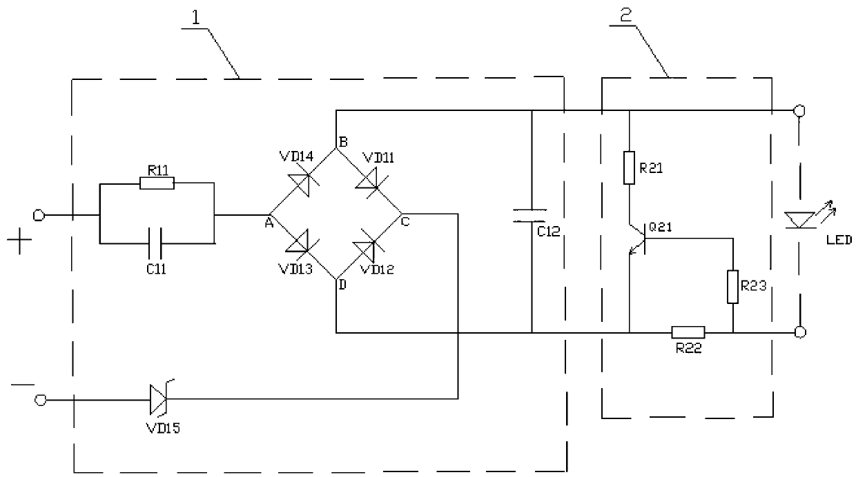
[0012] A constant current drive circuit for LED lights, such as figure 1 Shown: It includes the resistance-capacitance step-down circuit 1, which uses the capacitive reactance generated by the capacitor at the frequency of the AC signal to limit the maximum operating current of the LED lamp of the load, so as to ensure that the LED lamp will not burn out, and also includes the constant current circuit 2, which is connected to the Between the resistance-capacitance step-down circuit 1 and the LED lamp of the load, the current of the LED lamp can be kept constant, so as to prevent the LED lamp from burning out due to unstable external voltage.

[0013] Among them, the constant current circuit 2 is composed of a triode Q21 and three resistors R21, R22, and R23. One end of the resistor R21 and the current sampling resistor R22 are respectively connected to the anode and cathode of the output end of the RC step-down circuit 1, and the other end of the resistor R21 It is connected t...


PUM


Abstract

The invention relates to a drive circuit used for an LED (Light Emitting Diode) lamp, in particular to a constant-current drive circuit used for the LED lamp. The constant-current drive circuit used for the LED lamp comprises a resistance-capacitance voltage reducing circuit (1) and a constant-current circuit (2), wherein capacitive reactance generated by a capacitor under alternating current signal frequency is utilized to limit the maximum working current of the loaded LED lamp so as to ensure that the LED lamp is incapable of being overloaded to cause damages possibly; and the constant-current circuit is connected between the resistance-capacitance voltage reducing circuit (1) and the loaded LED lamp so as to cause the current of the LED lamp to be constant and prevent the LED lamp from being damaged possibly by instability of external voltage. The constant-current drive circuit used for the LED lamp can efficiently solve the technical problem that the drive circuit is bad in stability; when the external voltage is instable, the LED lamp can be prevented from being burnt so that the service life of the LED lamp is greatly prolonged; moreover, the constant-current drive circuit is simple in structure, low in production cost, simple in working procedure and high in rate of finished products; and the drive circuit used for the LDE lamp is good in application prospect.

Description

technical field [0001] The invention relates to a driving circuit for LED lamps, in particular to a constant current driving circuit for LED lamps. Background technique [0002] In the market, the general LED lamp driving circuit is a resistance-capacitance step-down circuit. This kind of circuit has poor stability. When the external voltage is unstable, it is easy to burn out the LED lamp and reduce the service life of the LED lamp. Due to the above shortcomings, some new LED lamp driving circuits have been developed. For example, the Chinese patent application No. 201019063019.X discloses a LED lamp driving circuit, which includes an AC / DC conversion circuit, a Transistor, twenty-second triode, twenty-third triode, twenty-fourth triode, twenty-first resistor, twenty-second resistor and diode, one end of comparator and AC / DC The conversion circuit is connected, the other end of the comparator is connected to the base of the twenty-first triode, the collector of the twenty-...

Claims


Application Information

Patent Timeline
Patent Type & Authority Applications(China)
IPC IPC(8): H05B37/02
Inventor 洪耀良
Owner HANGZHOU KEFAN LIGHTING ELECTRICAL APPLIANCE
Why Eureka
Try Eureka