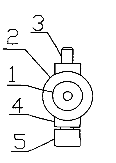
Lumbar puncture needle
A lumbar puncture and needle technology, applied in the field of puncture needles, can solve the problems of lack of visual visibility of cerebrospinal fluid, difficulty in precise control of cerebrospinal fluid flow, prolonging the puncture operation time, etc., to prevent the formation of induced brain herniation, save operation time, and use convenient effect
- Summary
- Abstract
- Description
- Claims
- Application Information
AI Technical Summary
Problems solved by technology
Method used
Image
Examples
Embodiment 1
[0039] like Figure 1 to Figure 15As shown, a lumbar puncture needle includes a needle 1, the needle 1 is provided with a needle lumen 24, the tail of the needle 1 is fixed on the handle 2, and the handle 2 is provided with a cavity and a valve handle; the cavity includes a handle inner cavity 6 , the handle lumen 25 and the threaded through hole 12, the left end of the handle lumen 6 communicates with the handle lumen 25, the right end of the handle lumen 6 communicates with the threaded through hole 12, the needle lumen 24 communicates with the handle lumen 25, and the inside of the handle The left end of chamber 6 is the tube lumen conical surface 7; Described valve handle comprises threaded rod 10, and the left end of threaded rod 10 is provided with integral valve handle cone 8, and the right end of threaded rod 10 is provided with integral turning handle 11, and described The threaded rod 10 is adapted to the threaded through hole 12, the threaded rod 10 passes through t...
Embodiment 2
[0051] like Figure 16 ~ Figure 18 As shown, the left end of the needle 1 is a closed cone 9, the outer wall of the needle adjacent to the cone 9 is provided with a liquid inlet 17, the liquid inlet 17 communicates with the needle lumen 24, and the liquid inlet 17 is a The axial long hole not only ensures that the needle has sufficient strength not to break, but also ensures a sufficient liquid inlet area to reduce the resistance of cerebrospinal fluid entering the needle 1 . Other structures are with embodiment 1.
[0052] Example 2 of the present invention uses the same method as Example 1.
Embodiment 3
[0054] like Figure 19 and Figure 20 As shown, embodiment 3 is the same as embodiment 1 except that pressure gauge 20 is used to replace the pressure measuring tube (hollow transparent pressure measuring tube 18 with upper and lower ends or sealed transparent pressure measuring tube 21) in embodiment 1. In this embodiment, the pressure gauge 20 is connected and fixed in advance through the internal thread of the interface of the pressure gauge and the external thread of the pressure measuring seat. In this embodiment, the pressure gauge can be a bellows pressure micro-pressure gauge (a pressure gauge measuring less than 60000Pa).
[0055] In Example 3 of the present invention, when measuring the pressure, the valve handle and the valve should be closed in advance, and the valve handle only needs to be unscrewed when measuring the pressure of the cerebrospinal fluid; the valve handle and the valve need to be unscrewed at the same time to collect the cerebrospinal fluid, and a...
PUM
 Abstract
Description
Claims
Application Information
 - R&D
- Intellectual Property
- Life Sciences
- Materials
- Tech Scout
- Unparalleled Data Quality
- Higher Quality Content
- 60% Fewer Hallucinations
Browse by: Latest US Patents, China's latest patents, Technical Efficacy Thesaurus, Application Domain, Technology Topic, Popular Technical Reports.
© 2025 PatSnap. All rights reserved.Legal|Privacy policy|Modern Slavery Act Transparency Statement|Sitemap|About US| Contact US: help@patsnap.com


