
Cutting blade and processing method thereof

A technology of cutting blades and processing methods, which is applied to the accessories of toolholders, metal processing equipment, turning equipment, etc., can solve the problems of difficult control of machining accuracy, high production cost of blades, and long cutting cycle, so as to reduce chipping Phenomenon, easy control of cutting direction, simple processing method

Inactive Publication Date: 2013-04-03
ZHUZHOU PURUIKE CEMENTED CARBIDE
View PDF8 Cites 2 Cited by
  • Summary
  • Abstract
  • Description
  • Claims
  • Application Information

AI Technical Summary

Problems solved by technology

Rounding treatment has the ability to strengthen the impact resistance of the blade. However, the cutting resistance of the rounded blade in the cutting process is large. When cutting metal, the machining accuracy is difficult to control, and the cutting cycle is longer; at the same time, the rounded Chemical treatment requires special equipment for processing, and the production cost of the blade is high

Method used


Image

  • Cutting blade and processing method thereof
  • Cutting blade and processing method thereof

Examples


Embodiment 1

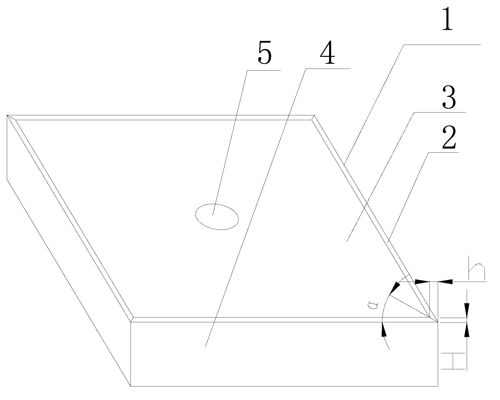
[0027] combine figure 1 , a cutting blade, comprising a blade body 1, the blade is provided with a blade portion, the blade portion is a chamfered edge structure, the chamfered edge structure forms an inclined plane 2, and the two ends of the inclined plane 2 are respectively connected to the rake face 3 and the rear face of the blade The knife face is 4, and the width of the chamfer is 0.15-1mm. Such as figure 1 , the width of the chamfer is H, h, that is, the vertical width and the horizontal width of the chamfer. The specific chamfer widths H and h are determined according to the size and application field of the blade.

[0028] The blade is a chamfered structure, so that the connection between the rake face and the flank face of the blade forms a transitional oblique plane. When cutting metal, the blade exerts a cutting external force on the workpiece, and the oblique plane of the chamfered structure contacts the workpiece. Compared with the rounded cutting edge in the ...

Embodiment 2

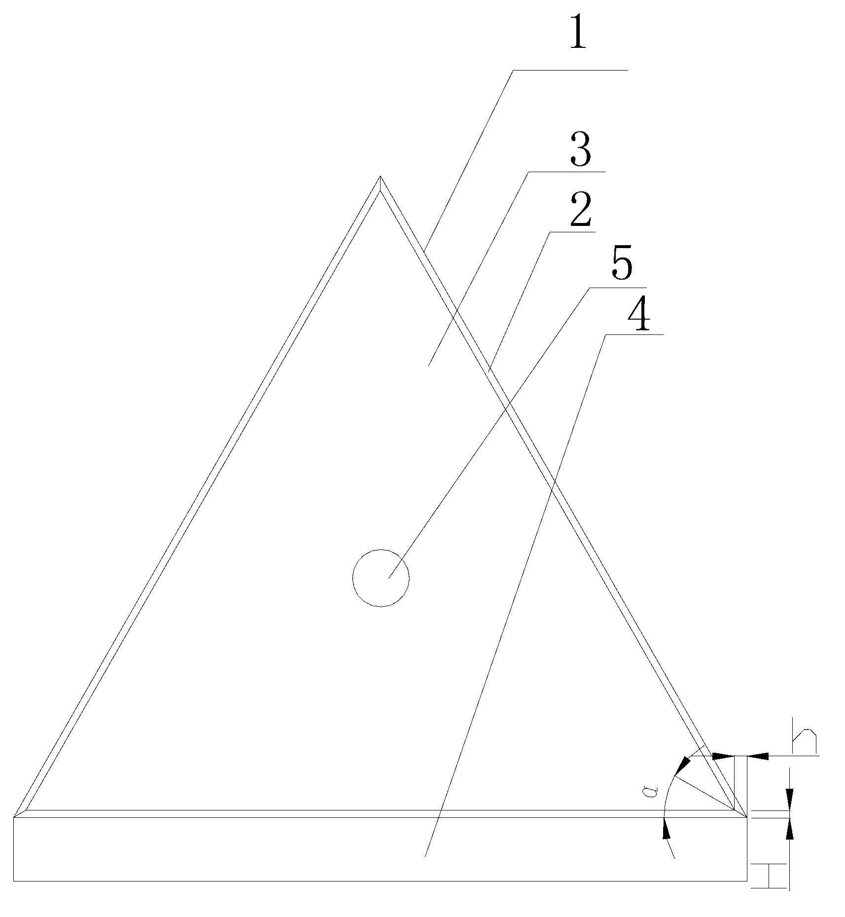
[0039] combine figure 2 , a cutting blade, comprising a blade body 1, the blade is provided with a blade portion, the blade portion is a chamfered edge structure, the chamfered edge structure forms an inclined plane 2, and the two ends of the inclined plane 2 are respectively connected to the rake face 3 and the rear face of the blade The knife face is 4, and the width of the chamfer is 0.15-1mm. Such as figure 2 , the width of the chamfer is H, h, that is, the vertical width and the horizontal width of the chamfer. The specific chamfer widths H and h are determined according to the size and application field of the insert.

[0040] The angle between the inclined plane and the horizontal plane is preferably 10-60 °, and the angle between the inclined plane and the horizontal plane is as follows figure 1In α, the inclination of the inclined plane is within this range, and the blade edge can easily apply cutting force to the workpiece. When the included angle between the i...


PUM

PropertyMeasurementUnit
widthaaaaaaaaaa

Abstract

The invention discloses a cutting blade and a processing method thereof. The cutting blade comprises a blade body; an edge is arranged on the blade and is of a chamfering structure; the chamfering structure forms an inclined plane; the two ends of the inclined plane are respectively connected with a front blade face and a rear blade face of the blade; and the width of the chambering structure is 0.15-1 mm. The cutting blade and the processing method disclosed by the invention has the beneficial effects that the cutting resistance of the cutting blade is small, the workpiece processing accuracy is high, the processing method of the cutting blade is simple, and the production cost is low.

Description

technical field [0001] The invention relates to the field of cemented carbide tools, in particular to a cutting blade and a processing method thereof. Background technique [0002] In mechanical metal cutting, cemented carbide inserts are widely used due to their advantages of large cutting volume and large cutting volume. In the prior art, the processing technology of the cutting insert has a rounding treatment step at the position of the cutting edge, and the rounding treatment connects a circular arc surface between the rake face and the flank face of the insert. The rounding treatment has the ability to strengthen the impact resistance of the blade. However, the cutting resistance of the rounded blade in the cutting process is large. When cutting metal, the machining accuracy is difficult to control, and the cutting cycle is longer; at the same time, the rounded Chemical treatment requires special equipment for processing, and the production cost of the blade is high. ...

Claims


Application Information

Patent Timeline
Patent Type & Authority Applications(China)
IPC IPC(8): B23B27/00B23P15/30
Inventor 李骏叶典舞张庭辉方伟清
Owner ZHUZHOU PURUIKE CEMENTED CARBIDE
Learn More