Elevator energy-saving system and control method thereof

An energy-saving system and control method technology, which is applied to collectors, electric vehicles, electrical components, etc., can solve the problems that the energy storage device cannot timely and flexibly respond to changes in the environment in which the elevator is used, and the cost increases, so as to achieve energy-saving and high-efficiency elevators. The effect of the elevator's ability to continuously regenerate

Active Publication Date: 2013-04-03
SHANGHAI MITSUBISHI ELEVATOR CO LTD
View PDF9 Cites 13 Cited by
  • Summary
  • Abstract
  • Description
  • Claims
  • Application Information

AI Technical Summary

Problems solved by technology

[0007] The technical problem to be solved by the present invention is to provide an elevator energy-saving system that can effectively utilize the regenerative energy without increasing the storage capacity of the energy storage device, and at the same time overcome the cost increase caused by the addition of a converter in the existing disclosed technology, which cannot be flexibly To cope with the changes in the environment in which the elevator is used and when the elevator stops running, the energy storage device cannot be discharged, the energy storage device cannot be discharged in a timely, rapid and reliable manner, and the time interval setting is complicated, etc.

Method used


Image

  • Elevator energy-saving system and control method thereof
  • Elevator energy-saving system and control method thereof
  • Elevator energy-saving system and control method thereof

Examples


Embodiment 1

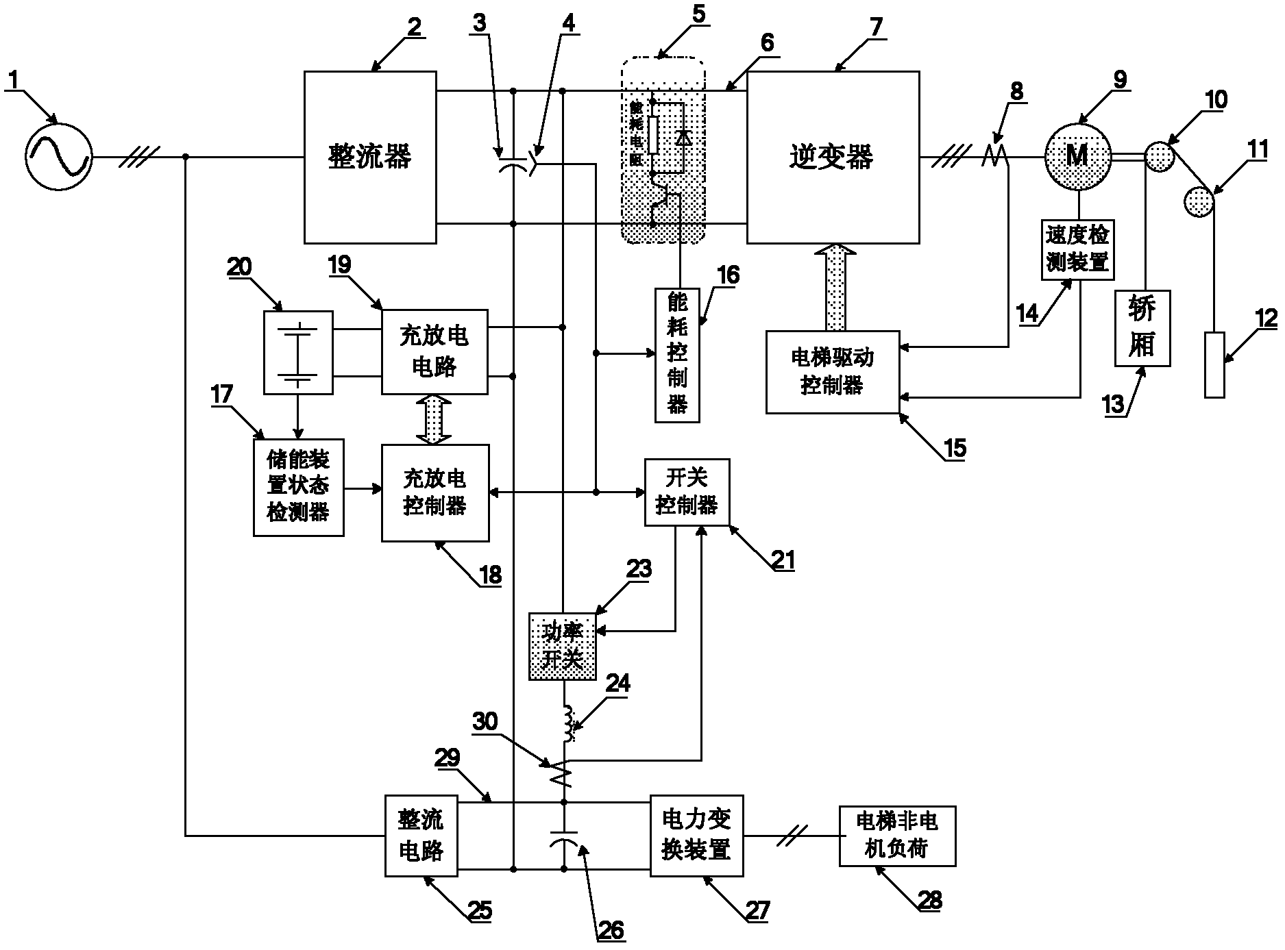
[0086] see figure 1 , in the first embodiment of the elevator energy-saving system, the external power supply 1 is connected to the three-phase AC side of the rectifier 2, and the DC side of the rectifier 2 is connected to the DC side input end of the inverter 7 through the first DC bus 6, smooth The DC capacitor 3 and the energy consumption circuit 5 are respectively connected across the two ends of the first DC bus 6, the bus voltage detector 4 is arranged at both ends of the smoothing DC capacitor 3, and the three-phase AC side of the inverter 7 passes through the current detector 8 is connected with the elevator motor 9, the elevator motor 9 is connected with the traction wheel 10 through a specific structure, the car 13 and the counterweight 12 are suspended on both sides of the traction wheel 10 and the guide wheel 11 by ropes. The elevator drive controller 15 generates a pair of inverters 7 according to the landing call, the car command or the deployment command of the ...

Embodiment 2

[0120] see Figure 4 , the second embodiment of the elevator energy-saving system is similar to the first embodiment, so only the differences will be described below.

[0121] The elevator motor state recognizer 31 is connected with the elevator driving controller 15, the charging and discharging controller 18 and the switch controller 21 through signal lines. The charging and discharging controller 18 for controlling the energy flow between the first DC bus 6 and the energy storage device 20 communicates with the energy storage device state detector 17, the bus voltage detector 4, and the elevator motor state recognizer 31 through signal lines It is connected to the charging and discharging circuit 19. The switch controller 21 for controlling the on and off of the power switch 23 is connected with the bus voltage detector 4, the current detector 30, the elevator motor state recognizer 31 and the power switch 23 through signal lines.

[0122] The elevator motor state recogni...

Embodiment 3

[0137] The overall structure of this embodiment is as Figure 6 as shown, with figure 1 The only difference in the overall structure of the first embodiment shown is that a power failure and recovery detector 33 for detecting the power supply state of the external power supply 1 (ie whether it is normal power supply or power supply stopped) is added.

[0138] The charging and discharging controller 18 controls the charging and discharging circuit 19 by the charging and discharging controller control method described in the first embodiment;

[0139] The switch controller 21 has two control modes according to the detection result of the power failure recovery detector 33:

[0140] Normal control mode: when the power failure and recovery detector 33 detects that the external power supply 1 is normally powered, the switch controller 21 detects the bus voltage V at both ends of the first DC bus 6 detected by the bus voltage detector 4 dc and its command value V dcref 1. The DC ...


PUM


Abstract

The invention discloses an elevator energy-saving system, which comprises an energy storage device, a charging and discharging controller and a rectification circuit, wherein an alternating current side of the rectification circuit is electrically connected with an external power source, or is electrically connected with the other alternating current power source independent from the external power source; a switch controller is respectively connected with a bus voltage detector, a current detector and a power switch through signal lines; and turning on and off of the power switch are controlled by the switch controller, so that transmission of regenerated energy to a second direct current bus can be realized, so as to supply power to non-motor load of an elevator. With the adoption of the elevator energy-saving system and the control method thereof, not only can the regenerated energy be stored when a motor of the elevator is in a regenerated state, and is the stored energy released to the first direct current bus to provide electric energy for the motor of the elevator, so as to realize energy saving of the elevator when the motor of the elevator is in an electrical state, but also the regenerated energy is preferentially provided to the non-motor load of the elevator, so as to improve the ability of continuously regenerating of the energy storage device corresponding to the elevator. The elevator energy-saving system also discloses a control method of the elevator energy-saving system.

Description

technical field [0001] The invention relates to an elevator energy-saving system, in particular to an elevator energy-saving system utilizing an energy storage device to realize elevator energy conservation. The invention also relates to a control method of the elevator energy-saving system. Background technique [0002] In recent years, it has become a research hotspot in the elevator industry to use energy storage devices to solve the problem of processing the regenerative energy generated during the operation of elevator motors, and to realize elevator energy saving at the same time. Because in some special occasions, the elevator will appear continuous regenerative operation. In this case, if the capacity of the energy storage device configured by the elevator is small, the problem that the regenerative energy generated after the energy storage device is fully charged cannot be stored and reused will occur due to the capacity limitation of the energy storage device. Th...

Claims


Application Information

Patent Timeline
Patent Type & Authority Applications(China)
IPC IPC(8): B66B1/06H02J7/02
Inventor 陈玉东
Owner SHANGHAI MITSUBISHI ELEVATOR CO LTD
Why Eureka
Try Eureka