Water retaining device

The technology of a water blocking device and a water plate is applied to the water discharge device and the field of water blocking, which can solve the problems of flexible loose-leaf, difficult replacement, maintenance and maintenance of the bottom water stop, and achieves the effects of low cost, saving investment and high structural rigidity.

Active Publication Date: 2013-04-03
YANGZHOU CHUMEN ELECTROMECHANICAL DEVICES MFG
View PDF8 Cites 11 Cited by
  • Summary
  • Abstract
  • Description
  • Claims
  • Application Information

AI Technical Summary

Problems solved by technology

The disadvantage is that it is difficult to replace and maintain the flexible loose-leaf and bottom water seal
Ther

Method used


Image

  • Water retaining device
  • Water retaining device
  • Water retaining device

Examples


Embodiment Construction

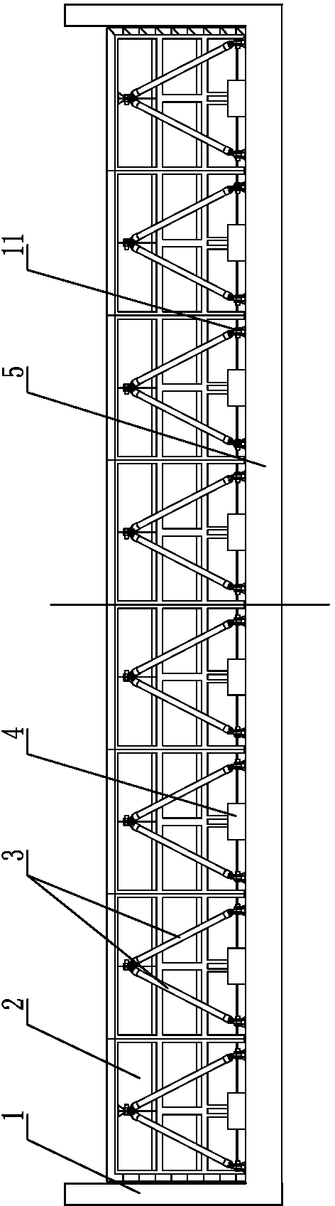
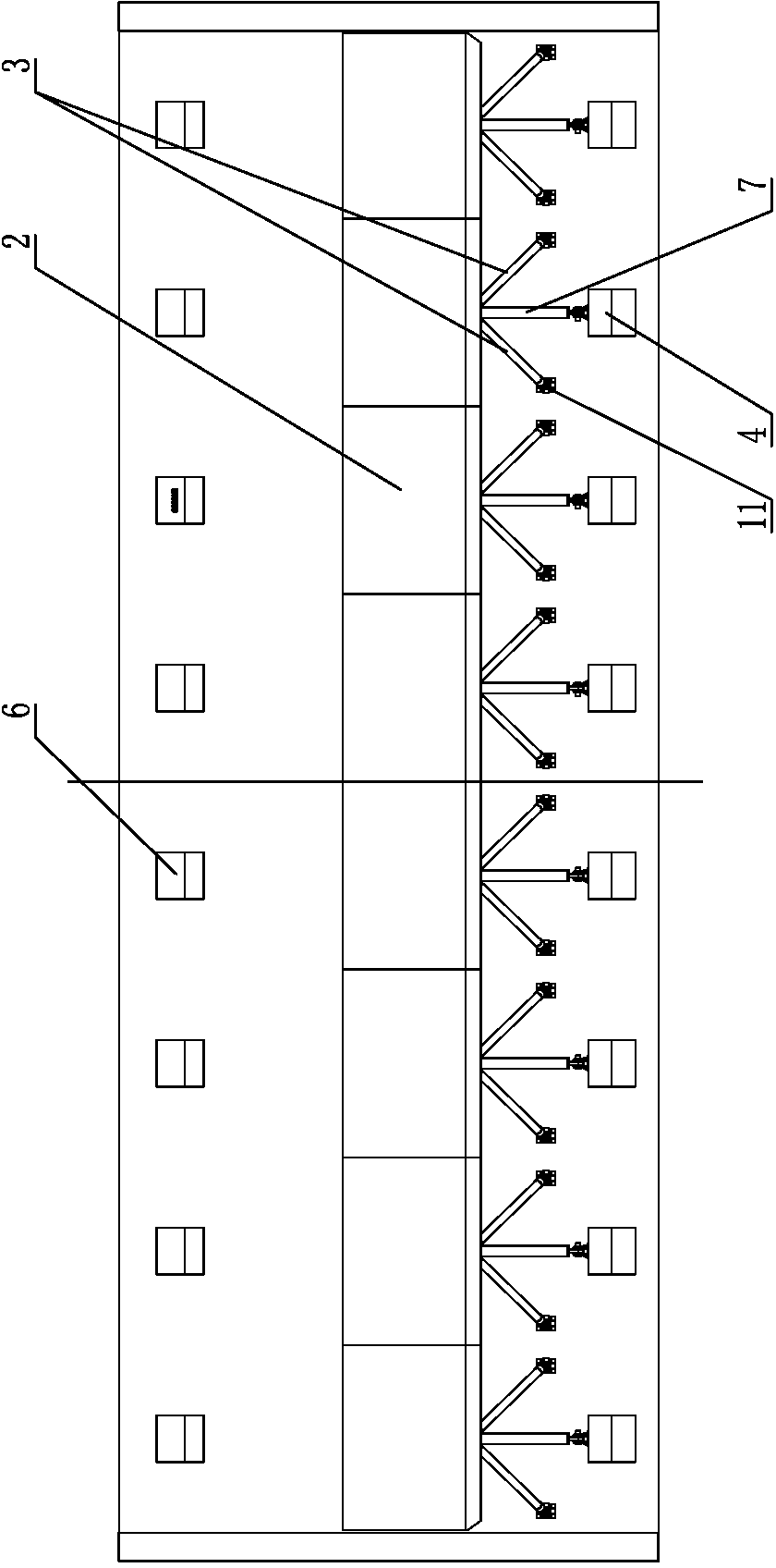
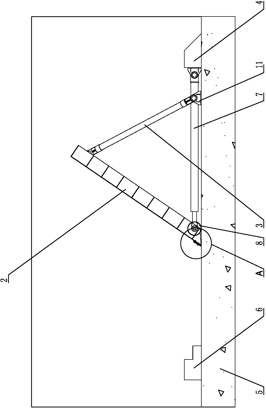
[0022] Such as Figure 1-4 As shown, it is a water blocking device, including several groups of water blocking boards 2, each group of water blocking boards 2 is welded by steel panels and steel beams; the water blocking boards are blocked in the river channel as a whole, and there are gate walls on both sides of the river 1. Concrete foundation 5 is provided at the bottom of the river channel, and side water stoppers are provided between adjacent groups of water blocking boards and between the side water blocking boards and the gate wall 1; the back water side of each group of water blocking boards 2 is The water blocking board is provided with a support pier 4 correspondingly, the bottom of the water blocking board 2 is provided with a roller 8 supported on the concrete foundation 5, an oil cylinder 7 is provided between the water blocking board 2 and the supporting pier 4, and the cylinder body is hinged on the supporting pier 4 On the top, the extended end of the piston ro...


PUM


Abstract

The invention discloses a water retaining device in the field of water conservancy facilities. The water retaining device comprises at least one group of water retaining boards which are integrally arranged in a watercourse, gate walls are arranged on two sides of the watercourse, a concrete foundation is arranged at the bottom of the watercourse, supporting piers are arranged on one sides of back faces of the water retaining boards in each group, rollers are arranged at the bottoms of the water retaining boards and supported on the concrete foundation, an oil cylinder is arranged between each water retaining board and the corresponding supporting pier, an oil cylinder block is hinged onto the corresponding supporting pier, and an extending end of an oil cylinder piston rod is hinged to the lower portion of the corresponding water retaining board. A hinge rod is further arranged on one side of the back face of each water retaining board, the upper end of each hinge rod is hinged to the upper portion of the corresponding water retaining board, and the lower end of each hinge rod is hinged onto a hinge seat which is fixed onto the concrete foundation. The water retaining device is high in structural strength, low in energy consumption, flexible in operation and investment-saving and can be used for various water conservancy constructions such as reservoir construction, watercourse flood flowing, urban water system management and agricultural irrigation.

Description

technical field [0001] The invention relates to a water conservancy facility, in particular to a device for blocking and releasing water in a river course. Background technique [0002] Compared with traditional gates such as flat doors, arc doors, horizontal sliding doors, and triangular doors, new types of gates have emerged in an endless stream in recent years. In the field of gates with small and medium spans, there are down gates (with and without arms), upturn gates, and straight gates. In the field of long-span gates, such as protective mirror doors, bottom horizontal-axis flap doors (steel dams), straight-lift doors with truss structures, lodging steel gates without middle piers (patent number: 200810014314.1), rubber dam steel gates (patent Application number: 200520087469.X), steel structure hydraulic automatic control flap gate (patent application number: 201010241022). Most of these gates are variants of traditional gates in terms of the force mode and opening ...

Claims


Application Information

Patent Timeline
IPC IPC(8): E02B7/20E02B7/54
Inventor 沈国华陈文珠陈文重
Owner YANGZHOU CHUMEN ELECTROMECHANICAL DEVICES MFG
Why Eureka
Try Eureka