Tunnel or roadway excavating method under weak and broken complicated geological conditions

A technology for complex geological conditions and tunnels, applied in tunnels, tunnel linings, underground chambers, etc., can solve problems such as advance support, and achieve the effects of fewer procedures and equipment, high efficiency, and simple operation

Inactive Publication Date: 2013-04-03
CENT SOUTH UNIV
View PDF4 Cites 12 Cited by
  • Summary
  • Abstract
  • Description
  • Claims
  • Application Information

AI Technical Summary

Problems solved by technology

[0005] The present invention adopts self-drilling steel drill, steel pipe or drill rod combined with steel arch frame to withstand the force from surrounding rock, thereby solving the problem of advanced support in tunnel or roadway excavation, and achieving the purpose of ensuring the formation and safe construction of tunnel or roadway

Method used


Image

  • Tunnel or roadway excavating method under weak and broken complicated geological conditions
  • Tunnel or roadway excavating method under weak and broken complicated geological conditions
  • Tunnel or roadway excavating method under weak and broken complicated geological conditions

Examples


Embodiment 1

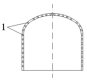
[0023] (1) Preparatory work: including clearing the pumice, leveling the working face 3, checking the rock mass of the working face 3, reasonably arranging the distance between the self-drilling steel drill 1, determining the reasonable length of the steel drill 1, estimating the amount of steel drill 1, and selecting the appropriate steel drill Arch frame 2, before operation, ensure that materials and equipment are in place, and prefabricated concrete pads.

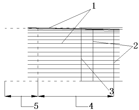
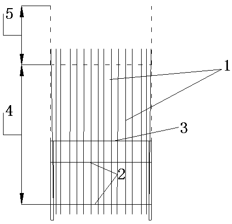
[0024] (2) Self-drilling steel drill 1 operation: Arrange the construction sequence of self-drilling steel drill 1, work continuously clockwise along the working surface, and control the camber angle of steel drill 1 to 4 o The length of the steel drill 1 passes through the muddy rock layer 4 and enters the stable rock formation 5. The steel drill 1 will be extended when drilling, and the length of a single steel drill 1 is 4m; Construction, self-drilling steel brazing 1 is no longer taken out after construction, and the...

Embodiment 2

[0029] (1) Preparatory work: including cleaning pumice, leveling the working face 3, checking the rock mass of the working face 3, reasonably arranging the distance between the self-drilling drill rod 1, determining the reasonable length of the drill rod 1, estimating the amount of the drill rod 1, and selecting the appropriate steel Arch frame 2, before operation, ensure that materials and equipment are in place.

[0030] (2) Self-drilling drill rod 1 operation: Arrange the construction sequence of self-drilling drill rod 1, work continuously counterclockwise along the working surface, and control the camber angle of drill rod 1 to 2 o , the length of the drill rod 1 passes through the weak and broken zone 4, and enters the stable rock formation 5. When the drill rod 1 is drilled, it will be extended, and the length of a single drill rod 1 is 4m; Construction, self-drilling drill rod 1 is no longer taken out after construction, and every drill rod 1 exposed length gets 350mm....


PUM


Abstract

The invention relates to the technical field of tunnel or roadway excavation, discloses a self-boring drilling steel, steel pipe or drill rod shed excavating method and particularly discloses a self-boring drilling steel, steel pipe or drill rod shed excavating method in a tunnel or roadway forepoling. The method overcomes the defects of a common pipe-shed method in construction of weak and broken rock strata, fault zones, rock strata degrading in water or collapse zones. The method includes the construction steps of first-phase preparations, self-boring drilling steel, steel pipe or drill rod operation, steel arch frame mounting, tunnel or roadway excavation and secondary supporting. Self-boring drilling steel, a steel pipe or a drill rod is capable of effectively forepoling unfavorable geologic bodies in front of a working surface, and constructed tunnel or roadway forming, construction speed and forepoling reliability are guaranteed. The method is capable of achieving forepoling of specially complicated rock masses and is wide in application range, simple to operate, few in occupied equipment and high in efficiency and safety.

Description

[0001] technical field [0002] The invention relates to a tunnel or roadway excavation and support method, in particular to a rapid excavation method under adverse geological conditions such as weakness, fragmentation, fault zone, severe mudification or landslide. Background technique [0003] When encountering special engineering conditions such as weak and broken rock formations, faults, cemented rock formations (such as iron, argillaceous shale) and landslides in tunnel or roadway excavation, pipe shed support technology is often used. However, the conventional pipe shed support method often has application limitations when encountering practical problems. For example, the conventional pipe shed method needs to form holes, but for the above-mentioned complex rock formations, it is often difficult to form holes; or grouting is required, but the injection The grouting takes a long time, which affects the progress of the project. For severely muddy surrounding rock, there a...

Claims


Application Information

Patent Timeline
Patent Type & Authority Applications(China)
IPC IPC(8): E21D11/00E21D9/00
Inventor 曹平张春阳蒲成志宁果果林杭
Owner CENT SOUTH UNIV
Why Eureka
Try Eureka