Method of quickly identifying crankshaft position

A crankshaft position, crankshaft technology, applied in engine control, machine/engine, electrical control, etc., to achieve high efficiency, fast transformation, and fast speed

Active Publication Date: 2013-04-03
UNITED AUTOMOTIVE ELECTRONICS SYST
View PDF7 Cites 8 Cited by
  • Summary
  • Abstract
  • Description
  • Claims
  • Application Information

AI Technical Summary

Problems solved by technology

This method is not optimal for camshaft signal wheels with multiple lobes

Method used


Image

  • Method of quickly identifying crankshaft position
  • Method of quickly identifying crankshaft position
  • Method of quickly identifying crankshaft position

Examples


Embodiment Construction

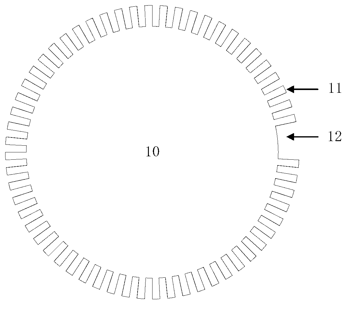
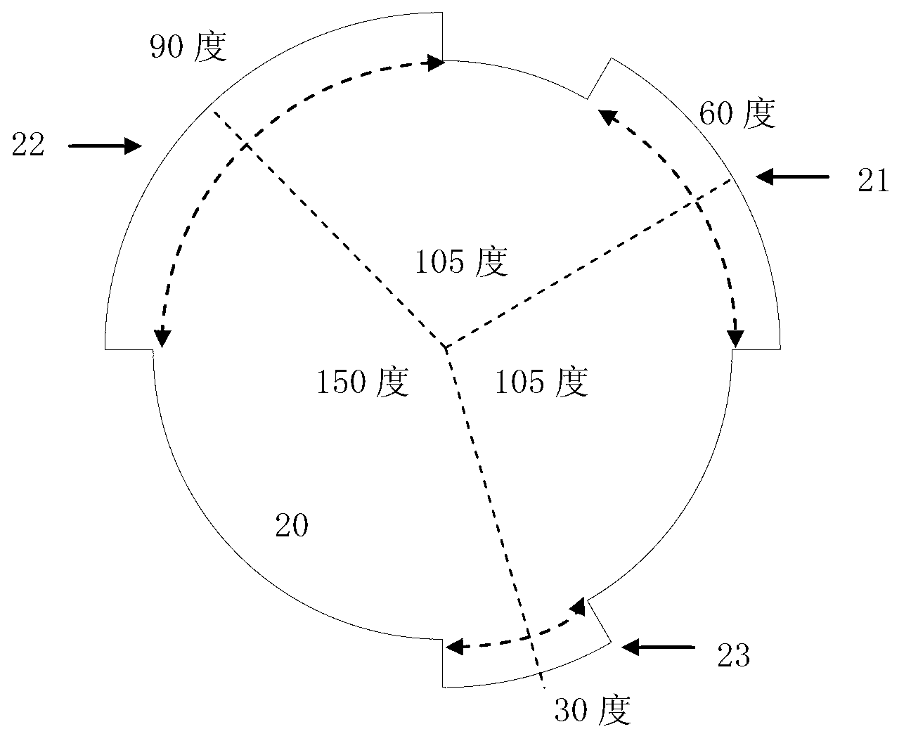
[0028] The applicable environment of this application is: a four-stroke engine, the crankshaft position sensor and the camshaft position sensor are Hall sensors. There are several normal teeth evenly distributed on the crankshaft signal wheel, and there is at least one missing tooth. The camshaft signal wheel has three lobes.

[0029] Typically, the engine builder installs the crankshaft signal wheel strictly to a parameter that specifies the angle at which the missing tooth position is from top dead center on the first cylinder. That is, when the engine is rotating, if the tooth-missing position is detected, it can be determined that the above-mentioned angle is the top dead center of the first cylinder (but because the crankshaft rotates twice in each working cycle of the engine, it is impossible to rely solely on this angle information to determine whether the top dead center is compression top dead center or exhaust top dead center)

[0030] see figure 1 , the crankshaf...


PUM


Abstract

The invention discloses a method of quickly identifying a crankshaft position, which skillfully utilizes signal features of a camshaft signal wheel provided with three convex teeth, and simultaneously detects if a level jump happens on the camshaft signal besides judging if missing teeth exist once one crankshaft signal falling edge is detected. If the current crankshaft signal does not miss teeth and the level jump happens on the camshaft signal, a level state of the following camshaft signal at a certain angle is continuously detected, and crankshaft angles under various conditions are finally determined, namely the identification of the crankshaft position is finished. Compared with a traditional crankshaft position identification method, the method can finish the identification of the crankshaft position before the missing teeth is discovered, so that the speed is quicker and the efficiency is higher.

Description

technical field [0001] The present application relates to a method for identifying the position of a crankshaft by an engine controller of a multi-cylinder four-stroke engine. Background technique [0002] Automobile engines usually use reciprocating piston internal combustion engines, including gasoline engines, diesel engines, etc. Each working cycle of these engines is composed of intake stroke, compression stroke, power stroke, and exhaust stroke, also known as four-stroke engines. During each working cycle, the crankshaft rotates 720 degrees and the camshaft rotates 360 degrees. [0003] What is actually used in automobiles is a multi-cylinder four-stroke engine. It is composed of several identical single cylinders arranged on one body and sharing a single crankshaft to output power. The common ones are four-cylinder, six-cylinder, eight-cylinder and so on. During the 720-degree rotation of the crankshaft, each cylinder completes a working cycle. [0004] In order to...

Claims


Application Information

Patent Timeline
Patent Type & Authority Applications(China)
IPC IPC(8): F02D45/00
Inventor 付宝军奚莉朱韬郝明德付逢春
Owner UNITED AUTOMOTIVE ELECTRONICS SYST
Why Eureka
Try Eureka