Shift multiplexing complex frequency domain optical coherence tomography scan detection method and system

An optical coherence tomography and detection method technology, which is applied in the field of shift multiplexing complex frequency domain optical coherence tomography scanning detection, can solve the problem of inability to realize the depth detection of samples, etc., and achieves improved detection imaging sensitivity, reasonable detection range, expansion Effect of Probing Depth Range

Active Publication Date: 2013-04-03
BEIJING UNIV OF TECH
View PDF8 Cites 8 Cited by
  • Summary
  • Abstract
  • Description
  • Claims
  • Application Information

AI Technical Summary

Problems solved by technology

[0006] The defect of the existing complex frequency domain OCT detection is that if the depth of the sample is greater than the maximum detection depth of the complex frequency domain OCT detection system, the detection of the entire sample depth cannot be realized

Method used


Image

  • Shift multiplexing complex frequency domain optical coherence tomography scan detection method and system
  • Shift multiplexing complex frequency domain optical coherence tomography scan detection method and system
  • Shift multiplexing complex frequency domain optical coherence tomography scan detection method and system

Examples


Embodiment Construction

[0033] Typical embodiments and features of the present invention will be described in detail below with reference to the accompanying drawings.

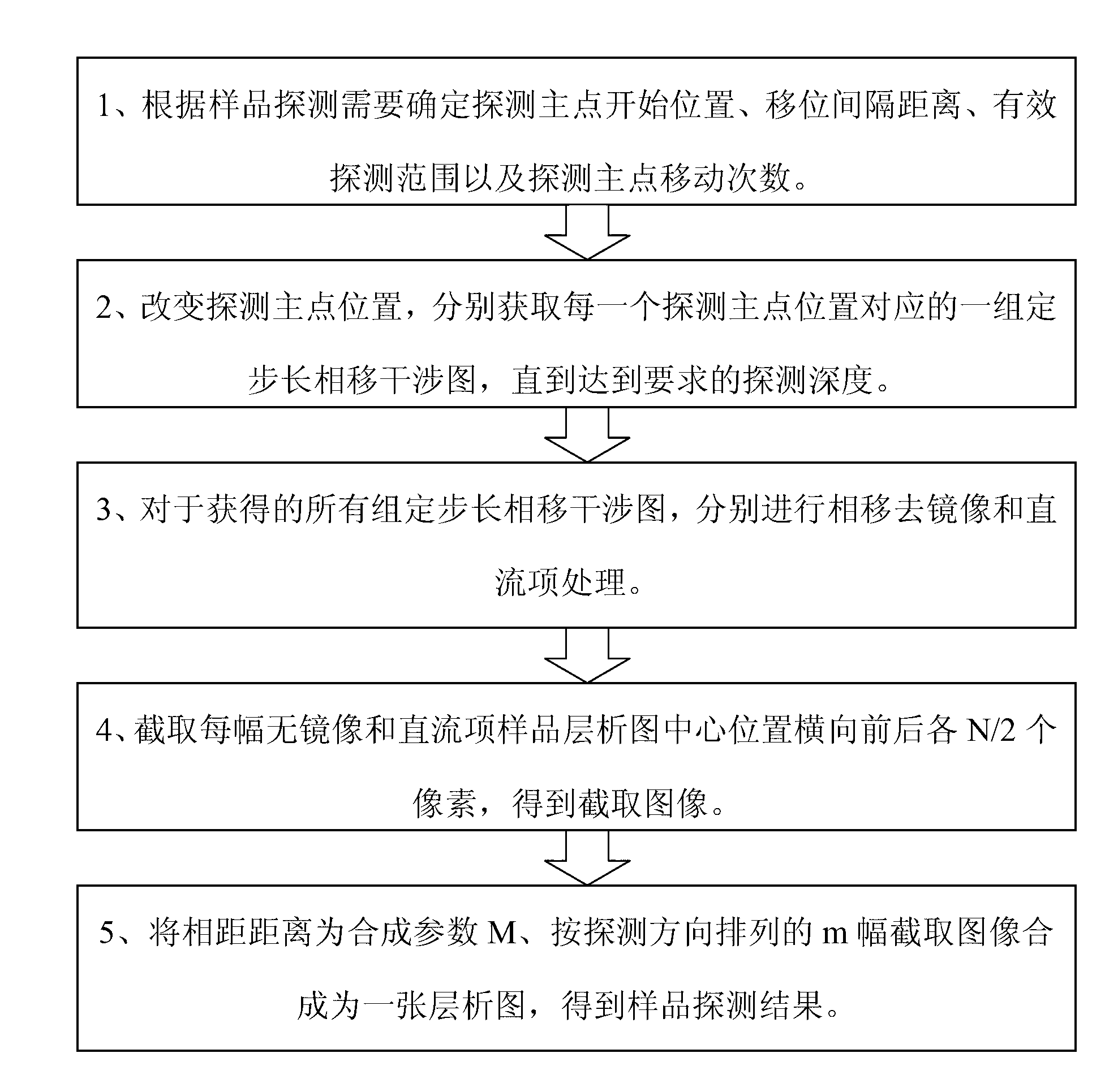
[0034] The shift multiplexing complex frequency domain optical coherence tomography detection method of the present invention, according to figure 1 The process shown in the figure, complete the following steps: 1) Determine the starting position of the main detection point, the displacement interval distance, the effective detection range, and the number of movement times of the main detection point according to the sample detection requirements; 2) Change the position of the main detection point, and obtain the A set of fixed-step-length phase-shift interferograms corresponding to the point position until the required detection depth is reached; 3) For all the obtained sets of fixed-step-length phase-shift interferograms, perform phase shift de-mirror and DC term processing; 4) Intercept each There are N / 2 pixels before and after t...


PUM

PropertyMeasurementUnit
refractive indexaaaaaaaaaa

Abstract

The invention relates to a shift multiplexing complex frequency domain optical coherence tomography scan detection method and a shift multiplexing complex frequency domain optical coherence tomography scan detection system. The shift multiplexing complex frequency domain optical coherence tomography scan detection system comprises an emitting light path system, a receiving light path system, a dispersion prism reflecting light path system and a dispersion prism transmitting light path system. The shift multiplexing complex frequency domain optical coherence tomography scan detection method comprises the following steps: through a mobile carrying translation stage, sequentially changing detection main point positions; for each detection main point position, performing phase shifting by using a piezoelectric ceramic translation stage, and acquiring a group of phase shift interferogram with a fixed step length till a required detection depth is achieved; for the acquired multiple groups of phase shift interferograms with the fixed step lengths, respectively performing phase shifting mirror image and direct current term removal to obtain m mirror image-free and direct current term-free sample chromatograms corresponding to the detection main point positions; and transversely intercepting front and back respective N / 2 pixels in a central position of each sample chromatogram respectively to obtain m intercepted images, and combining the m intercepted images which are arrayed in a detection direction into one chromatogram.

Description

technical field [0001] The present invention relates to a method and system for optical coherent imaging detection, in particular to a detection method and system for optical coherence tomography in shift multiplexing complex frequency domain. Background technique [0002] Optical coherence tomography, also known as optical coherence tomography (OCT for short), mainly uses the principle of interference to achieve depth information collection of samples. According to whether to scan in the depth direction, it can be divided into time-domain OCT and frequency-domain OCT. Time-domain OCT is a typical OCT system. By changing the optical path difference between the reference arm and the sample arm, the sample information at different depths can be detected. Since time-domain OCT is based on point-by-point scanning detection, each point measurement needs to move the reference arm to change the optical path difference between the reference arm and the sample arm, which consumes a ...

Claims


Application Information

Patent Timeline
Patent Type & Authority Applications(China)
IPC IPC(8): G01N21/45G01B11/22
Inventor 江竹青黄昊翀蔡文苑王羽佳
Owner BEIJING UNIV OF TECH
Why Eureka
Try Eureka