Analyzing method of pollutant absorption capability of deep UV (ultraviolet) fluoride film element

A technology of adsorption capacity and thin-film components, which is applied in the field of deep-ultraviolet optical technology applications, can solve the problems of insufficient internal structure of optical films, performance degradation of thin-film components, and increased absorption of deep-ultraviolet optical films to meet environmental applicability and timeliness Performance evaluation, the effect of high environmental adaptability

Inactive Publication Date: 2013-04-03
CHANGCHUN INST OF OPTICS FINE MECHANICS & PHYSICS CHINESE ACAD OF SCI
View PDF3 Cites 3 Cited by
  • Summary
  • Abstract
  • Description
  • Claims
  • Application Information

AI Technical Summary

Problems solved by technology

Using the hot boat evaporation preparation process, the deep ultraviolet fluoride optical film with small absorption can be obtained, but at the same time, it is accompanied by the shortcomings of the internal structure of the optical film is not dense enough, the surface of the optical film is rough, etc.
Therefore, the deep ultraviolet optical film prepared by the heat boat evaporation process, because the internal structure of the optical film is not dense enough and the surface of the optical film is relatively rough, the organic pollutants in the application environment will inevitably be absorbed, so that the deep ultraviolet optical film is used in the application environment. Performance degradation during use, which leads to performance degradation or even failure of thin-film components, which will have catastrophic consequences for the entire optical system
[0004] Studies have shown that the performance degradation of this deep ultraviolet optical film is concentrated in the absorption of organic pollutants and water vapor inside and on the surface of the deep ultraviolet optical film, resulting in a significant increase in the absorption of the deep ultraviolet optical film

Method used


Image

  • Analyzing method of pollutant absorption capability of deep UV (ultraviolet) fluoride film element

Examples


Embodiment 1

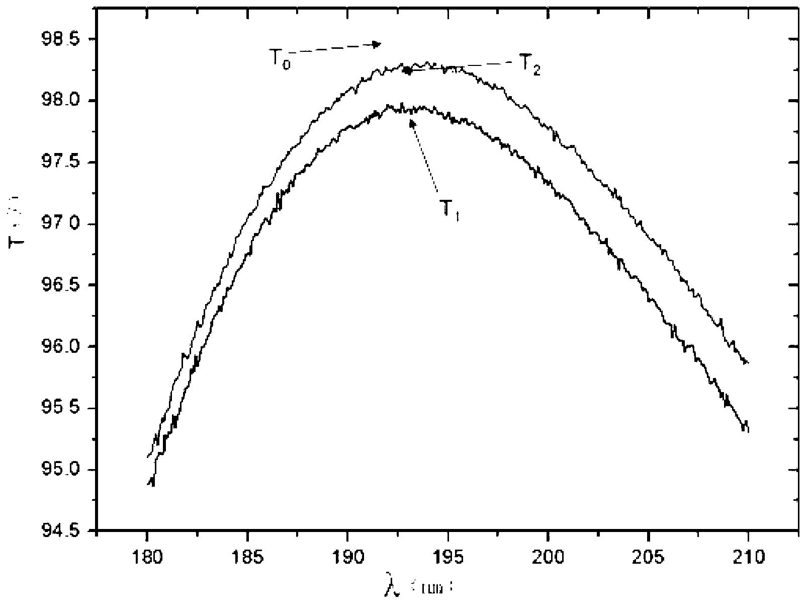
[0027] This example evaluates the adsorption capacity of organic pollutants and water vapor in a standard laboratory environment (temperature 22°C, relative humidity 30%) for a fluoride anti-reflection film prepared under the process parameters of heat boat evaporation.

[0028] Such as figure 1 Shown is a spectrum test evaluation chart of the laboratory environment organic pollutants and water vapor adsorption capacity of the deep ultraviolet fluoride anti-reflection film of the present invention.

[0029] Including that after the fluoride anti-reflection film is coated, the spectrophotometer is purged with high-purity N 2 Transmittance tested at 193nm band transmittance T 0 98.4% is used as the initial value of the spectral performance of the anti-reflection film sample.

[0030] After the thin film element was placed in the laboratory environment for 2 weeks, the spectrophotometer was in a vacuum environment (P-6 mbar) to test the transmittance of the sample in the 193nm ...


PUM


Abstract

The invention discloses an analyzing method of pollutant absorption capability of a deep UV (ultraviolet) fluoride film element, and belongs to the field of deep UV optics technology applications. The method comprises the following steps of: 1. testing the reflectivity R0 or transmittance T0 of a fluoride film sample after primary plating; 2. testing the reflectivity R1 or transmittance T1 after the sample absorbs organic matters or water vapor after the fluoride film sample is placed in an application environment system and is used or stored for a period of time; 3. carrying out low-power energy density irradiation on the surface of the sample by an ArF excimer laser, purging the dry high-purity N2 in the whole optical path system, and meanwhile monitoring the transmission laser energy by an energy meter; 4. carrying out spectrum testing on the sample after laser irradiation by the ArF excimer laser, thereby obtaining the reflectivity R2 or transmittance T2 of the sample after laser irradiation; and 5. operating an absorption factor Eta by the formula that Eta=Eta1+Eta2=(T2-T1)/T1+(T0-T2)/T0.

Description

technical field [0001] The invention relates to an analysis method applicable to the pollutant adsorption capacity of deep ultraviolet fluoride thin film elements, belonging to the application field of deep ultraviolet optical technology. Background technique [0002] The development of integrated circuit technology has greatly promoted the progress of human information society, and has become one of the key core technologies in the development of modern high technology. Significant social and economic value. In recent years, 193nm ArF excimer lasers have been widely used as light sources for deep ultraviolet lithography machines. The continuous development of deep ultraviolet laser optical systems and applications poses new challenges to the performance and long-term stability requirements of deep ultraviolet optical thin film components. [0003] The fundamental problem facing the research of deep ultraviolet optical thin films is that because the deep ultraviolet band i...

Claims


Application Information

Patent Timeline
Patent Type & Authority Applications(China)
IPC IPC(8): G01N21/47G01N21/59
Inventor 金春水靳京城李春邓文渊常艳贺
Owner CHANGCHUN INST OF OPTICS FINE MECHANICS & PHYSICS CHINESE ACAD OF SCI
Why Eureka
Try Eureka