Supercharge Your Innovation With Domain-Expert AI Agents!

Bridge rectifier automatic testing machine

An automatic testing machine and testing agency technology, applied in the direction of testing dielectric strength, measuring electricity, measuring devices, etc., can solve the misjudgment of testing equipment, the inability to perform initial testing and retesting at the same time, and the bridge stack is incorporated into an inverted "V" shape. The problem of the same position in the groove, etc., can ensure the accuracy and reliability, reduce the manual placement process, and reduce the labor intensity.

Active Publication Date: 2013-04-03
乐山希尔电子股份有限公司
View PDF10 Cites 8 Cited by
  • Summary
  • Abstract
  • Description
  • Claims
  • Application Information

AI Technical Summary

Problems solved by technology

But in actual use, this patent still has the following defects: one, the pins of the bridge stack are arranged horizontally during the test, and the test probe is pressed from top to bottom on the pins of the bridge stack to be tested. To complete the test of the upper layer pins arranged horizontally, it is necessary to repeat the above steps to test the lower pins again, which has a narrow scope of application and low test efficiency; two, the initial test and retest cannot be carried out at the same time, and the test efficiency is low; three, when When the test encounters defective products, there is no special collection box for defective products, which will easily lead to the mixing of defective products and qualified products; 4. During the test, the inverted "V" groove connected to the piston shaft is driven by the test cylinder to move downward, and The bridge stack is put into the inverted "V" groove for testing, and the bridge stack is not limited during the process of transporting the bridge stack to the test position. Therefore, the bridge stack is easy to fall from the conveying track, and it cannot be guaranteed The bridge stack can be incorporated into the same position in the inverted "V" groove, and the test probe may not touch the pin test point at the same time or the test probe touches its position, not only the accuracy of the test is low, but also the test Equipment misjudgment
But this scheme can't be applied to the test to the square bridge stack in this field at all, thus still has not solved the above-mentioned existing problem

Method used


Image

  • Bridge rectifier automatic testing machine
  • Bridge rectifier automatic testing machine
  • Bridge rectifier automatic testing machine

Examples


Embodiment 1

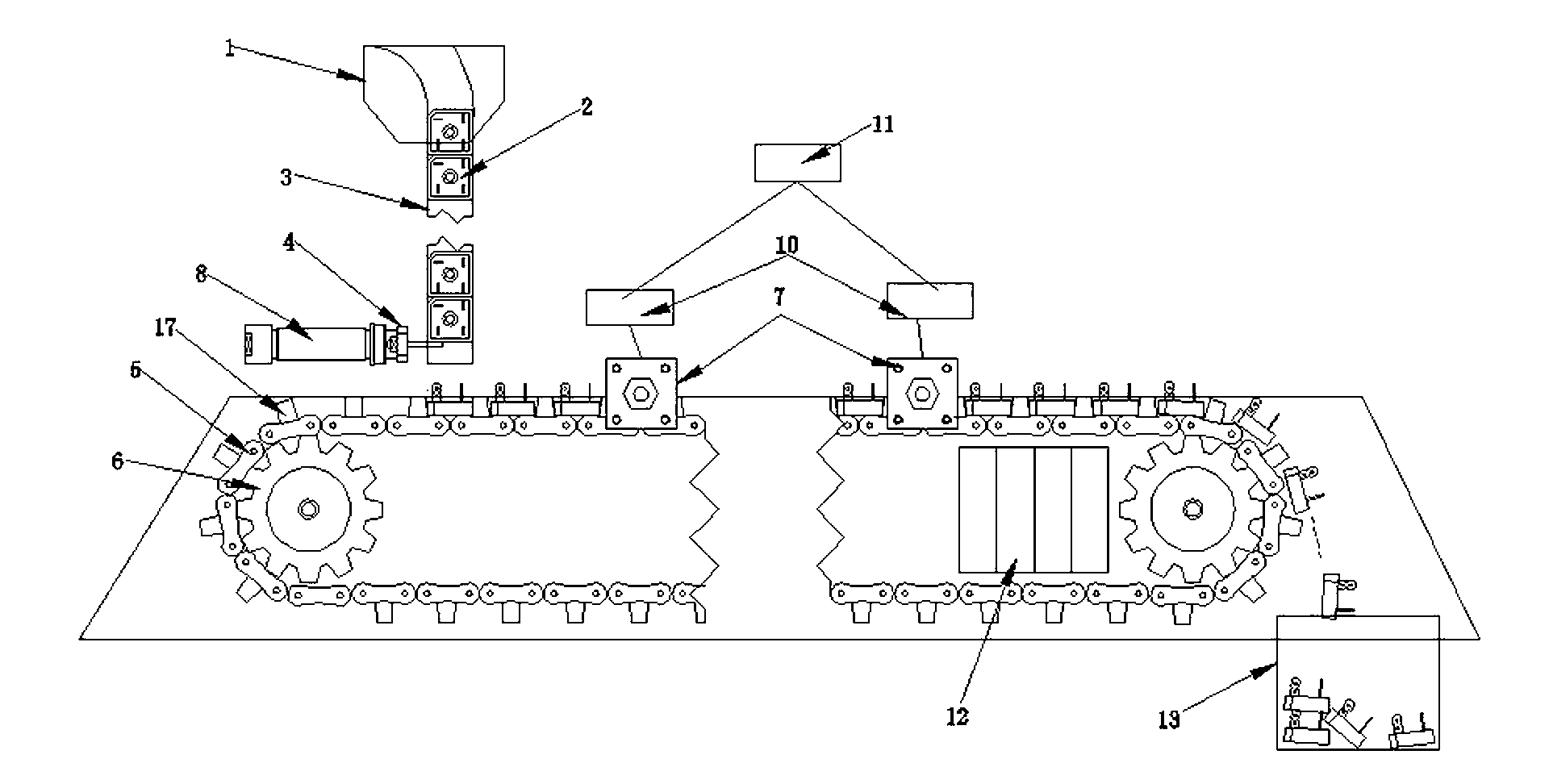
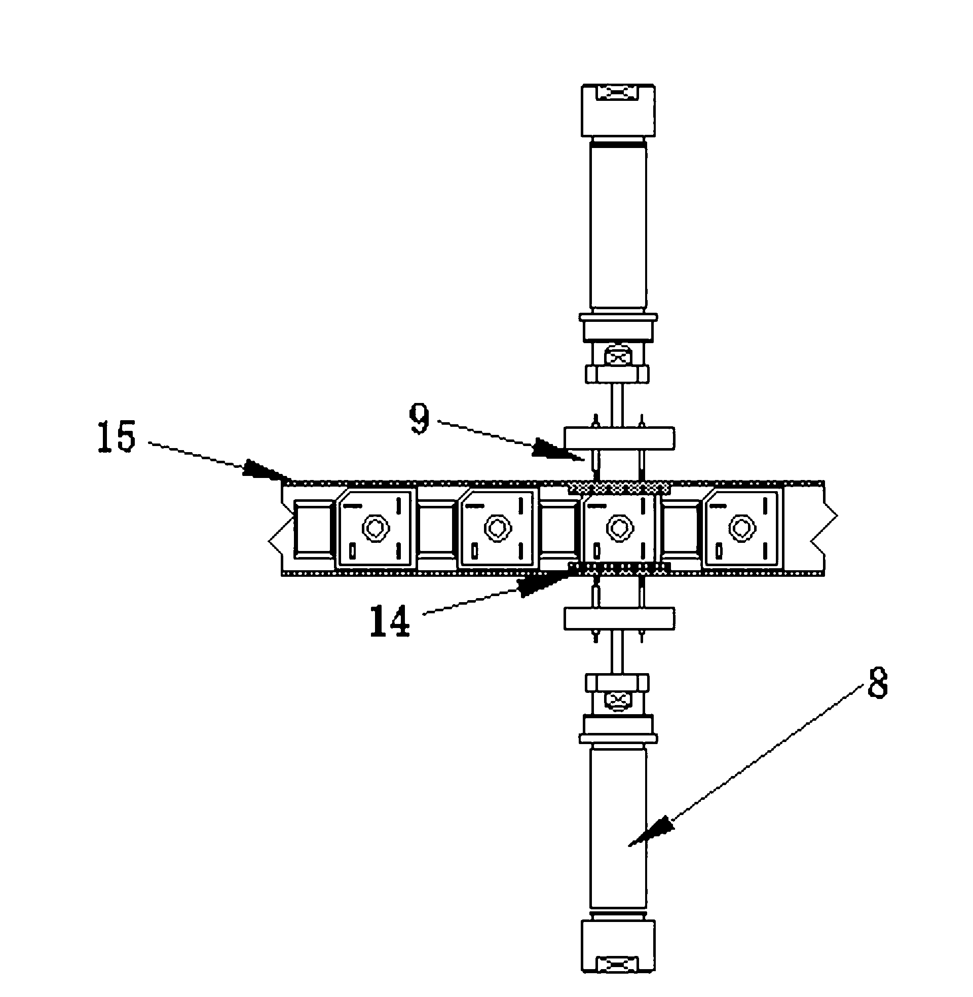
[0039] An automatic testing machine for bridge piles, comprising a test feeding track 5, a stepping motor 6, a feeding mechanism, a data acquisition instrument and a testing mechanism 7, the test feeding track 5 is a ring structure, and is driven by a stepping motor 6 for circulation Rotate, the surface of the test feeding track 5 is provided with a gap arrangement of the limit groove 17, the limit groove 17 matches the shape of the plastic package of the bridge stack 2, and the discharge port of the feeding mechanism corresponds to the limit groove 17 , the testing mechanism 7 includes a primary testing mechanism 7 and a retesting testing mechanism 7, and each set of testing mechanism 7 includes a testing instrument 10, two cylinders 8 and test probes 9, and the two cylinders 8 are set at the limit On both sides of the groove 17, the test probe 9 is fixed on the end of the cylinder piston, and the test probe 9 corresponds to the test point 16 on the pin of the bridge stack 2, ...

Embodiment 2

[0045] This embodiment is basically the same as the above-mentioned embodiment, the main difference is:

[0046] In this embodiment, it is preferable that the limiting groove 17 is formed by a limiting block arranged on the surface of the test feeding track 5 with a gap, and the bottom surface of the limiting groove 17 is parallel to the ground to ensure that the bridge stack 2 is on the testing feeding track 5 Its pins are arranged vertically upward and regularly, which is convenient for testing with the test probe 9 .

[0047] In this embodiment, it is preferable that the limit block is square, but it is not limited to the above arrangement. For example, the limit block can be semicircular or other shapes, so as to test bridge stacks whose plastic bodies are circular or other shapes. 2. Preferably, the limit block is clamped and connected to the test feeding track 5, but it can also be connected by a plug connection or a bolt, so as to facilitate changing the distance betwee...

Embodiment 3

[0050] This embodiment is basically the same as the above-mentioned embodiment, the main difference is:

[0051] In this embodiment, preferably four limit anti-turnover plates 14 are symmetrically arranged on both sides of the test feeding track 5, wherein, every two symmetrical limit and anti-turnover plates 14 correspond to a set of testing mechanism 7, and the position limit The number of anti-overturning plates 14 can be 6, 8 or more, to reserve a place for adding the test mechanism 7 in the future, and to meet the requirements of the second or more tests;

[0052] Further, it is preferable to set a through hole on the limit anti-turnover plate 14, so that the test probe 9 can pass through the through hole to test the pins of the bridge stack 2.

[0053] In this embodiment, preferably, the height of the limiting anti-turnover plate 14 is the same as the length of the pins.


PUM


Abstract

The invention discloses a bridge rectifier automatic testing machine, which comprises a testing feeding rail, a stepping motor, a feeding mechanism, a data acquisition instrument and a testing mechanism, wherein the testing feeding rail is in an annular structure which is driven to cyclically rotate by the stepping motor; limiting grooves are distributed on the surface of the testing feeding rail at intervals; the limiting grooves are matched with a plastic package body of a bridge rectifier in shape; the material outlet of the feeding mechanism corresponds to the limiting grooves; the testing mechanism comprises a primary testing mechanism and a secondary testing mechanism, and each set of the testing mechanisms is composed of a testing instrument, two cylinders and testing probes; the two cylinders are arranged at two sides of the limiting grooves; the testing probes are fixed at the ends of cylinder pistons, and correspond to testing points on bridge rectifier pins; and each of the testing instruments is connected with each of the testing probes. According to the bridge rectifier automatic testing machine, the pins of the bridge rectifier to be tested are vertically distributed upwards, so that the primary performance testing and secondary testing of the bridge rectifier are automatically completed in one time; and therefore, the accuracy and reliability of the testing are guaranteed, and the testing efficiency is greatly improved.

Description

technical field [0001] The invention relates to a testing device, in particular to a bridge pile automatic testing machine. Background technique [0002] In the production of bridge stacks, the produced bridge stacks need to undergo a secondary performance test, that is, preliminary testing and retesting, and can only be sold after passing the test. At present, because the bridge stack has at least four pins, the bridge stack The test method is mainly to manually insert the products into the shrapnel test tool one by one. After a batch of tests are completed, retests will be carried out, resulting in extremely low overall production efficiency of the bridge stack, and manual operation can not only guarantee the reliability of the test, It is also easy to cause defective products to be missed or misplaced. At the same time, manual testing is used, which has high labor intensity, low testing efficiency, and high production costs. [0003] In order to solve the above problems,...

Claims


Application Information

Patent Timeline
IPC IPC(8): G01R31/00G01R31/12B07C5/38
Inventor 邓华鲜
Owner 乐山希尔电子股份有限公司
Features
  • R&D
  • Intellectual Property
  • Life Sciences
  • Materials
  • Tech Scout
  • Unparalleled Data Quality
  • Higher Quality Content
  • 60% Fewer Hallucinations
Learn More