
Connector product test device

A technology for product testing and testing devices, applied in the direction of measuring devices, measuring device casings, instruments, etc., can solve the problems of cumbersome testing process, increase testing cost, low work efficiency, etc., reduce testing cost, improve clamping accuracy, test Efficiency improvement effect

Active Publication Date: 2013-04-03
珠海市运泰利自动化设备有限公司
View PDF7 Cites 23 Cited by
  • Summary
  • Abstract
  • Description
  • Claims
  • Application Information

AI Technical Summary

Problems solved by technology

However, this test method has the following disadvantages: 1. It is necessary to produce a matching test connector according to the specifications of the product connector, and the cost of this test connector is high, which increases the test cost; 2. The test process is cumbersome , It needs manual plugging and unplugging actions, and the work efficiency is low; 3. In the process of repeated plugging and unplugging of the test connector, due to the high friction of the contact area, it is easy to cause damage to the test connector, and it is difficult to repair after damage, and the overall service life is short
All in all, this test method has defects such as high cost of consumables, low test efficiency, and inconvenient maintenance.

Method used


Image

  • Connector product test device
  • Connector product test device
  • Connector product test device

Examples


Embodiment 1

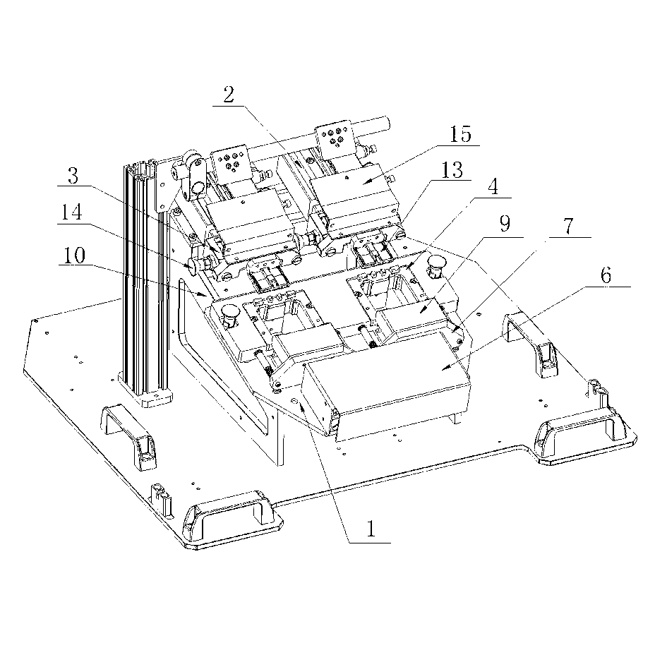
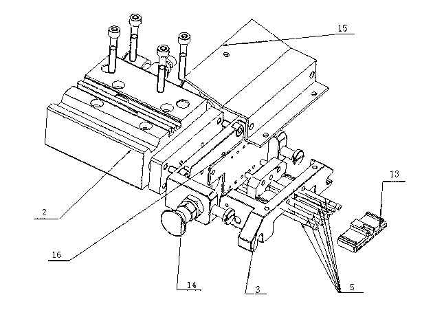
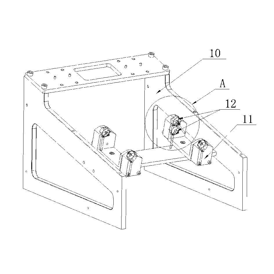
[0029] like Figure 1 to Figure 6 As shown, the present invention uses test pins to replace the test connectors of the prior art for testing operations, which includes a test terminal, a test device, a control circuit and a control button electrically connected to the control circuit, and the test terminal stores test data It is also used to record measurement data, and the control circuit and control buttons are used to control the specific actions and strokes of the relevant components of the present invention. The test device includes a support board 1 , a power unit I2 arranged on the support board 1 and a fixture seat 4 adapted to the connector to be tested. The power device I2 provides a power source, which can be a pneumatic device or a hydraulic transmission device or a hydraulic-pneumatic combination device. The power device I2 is electrically connected to the control circuit, so that the power device can be directly controlled by the control button Ⅰ2 specific actio...

Embodiment 2

[0037] This embodiment is the second technical solution of the present invention, and the design concept is the same as that of the first embodiment, which uses test pins instead of the prior art test connectors to test the product connectors, while this embodiment uses manual control.

[0038] like Figure 7 to Figure 10 As shown, the test machine of the present invention includes a test terminal 32 and a test device, the test device includes a base 20 and an upper cover 21 that is movably connected to the base 20, and the base 20 is provided with a Fixture seat 22, the side of the upper cover 21 facing the fixture seat 22 is provided with a test needle board 23, the outer side of the upper cover 21 is provided with an adapter plate 33 electrically connected to the test terminal 32, the transfer The connecting plate 33 has the same function as that in the first embodiment. The test needle plate 23 is provided with a suitable test needle 24, and the test needle 24 is electrica...


PUM


Abstract

The invention discloses a test device, in particular to a connector product test device which is high in test accuracy, reduces test cost and improves test efficiency. According to the connector product test device, a test pin is adopted to replace the test connector in the prior art for product testing, is arranged on a movable carrier and is electrically connected with a test terminal. During testing, the carrier moves by aid of manual operation or through a power device and drives the test pin to move in the direction of a connector to be tested, and finally the tail end of the test pin is contacted with a metal sheet of the connector to be tested to achieve testing. The connector product test device is widely applied to the connector test field.

Description

technical field [0001] The invention relates to a test device, in particular to a test device for high-quality connector products with high requirements for test accuracy, and is mainly oriented to industries such as precision electronics, automobiles, home appliances, and digital products. Background technique [0002] Connector is a common component for electronic engineers and technicians, and it is also an indispensable part in electronic products, automotive electronic products, home appliances and other products. Its function is to build a bridge of communication between the blocked or isolated circuits in the circuit, so that the current can flow and the circuit can realize the predetermined function. For example, our mobile phone charging interface is a simple connector through which current is input into the mobile phone battery for charging. In order to ensure the reliability and practicability of the connector, the finished connector must be strictly tested befor...

Claims


Application Information

Patent Timeline
Patent Type & Authority Applications(China)
IPC IPC(8): G01R31/00G01R1/04G01R1/067
Inventor 祝国昌
Owner 珠海市运泰利自动化设备有限公司
Learn More