Data conduction and positioning device for turnover light-emitting diode (LED) studio screen

A technology of conducting device and positioning device, which is applied to identification devices, instruments, etc., can solve the problems of data cable or wire damage, rigid display form, falling off of terminals, etc., and achieves long service life, convenient positioning and connection structure, and reasonable structure. Effect

Inactive Publication Date: 2013-04-03
CHANGSHA XINYUAN ELECTRONICS TECH
View PDF9 Cites 3 Cited by
  • Summary
  • Abstract
  • Description
  • Claims
  • Application Information

AI Technical Summary

Problems solved by technology

The data information required by the rotating LED triangle module is drawn out from the positioning device on the upper port through wires and connected to external equipment. Since the fixed object and the rotating object are directly connected by wires, in order to prevent wires from being entangled, only control Rotation angle and rotation method are used to solve the problem. The existing rotation method of the above-mentioned products is to flip back and forth, so there are the following defects: first, the front and back flips back and forth, and the display form is rigid; second, the data line or power line follows the LED triangle When the module rotates, it is easy to cause the terminal to fall off; the third is that the rotating data transmission wire rubs against the inner wall of the hollow shaft of the positioning device for a long time, which is easy to cause damage to the data line or wire; Objects are directly connected by wires. Once the machine loses control, the wires will be entangled and the wires will be damaged. Since the working current is generally between 30-50 amperes, it may cause a short circuit due to wire damage and cause a fire.

Method used


Image

  • Data conduction and positioning device for turnover light-emitting diode (LED) studio screen
  • Data conduction and positioning device for turnover light-emitting diode (LED) studio screen
  • Data conduction and positioning device for turnover light-emitting diode (LED) studio screen

Examples


Embodiment Construction

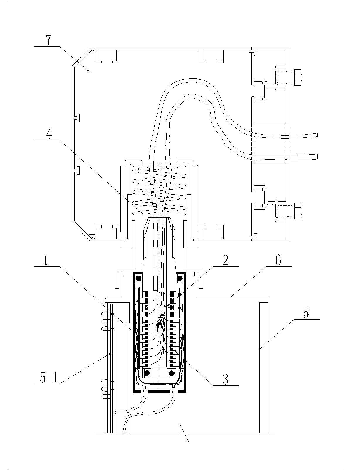
[0033] Data connection device (1) is implemented, such as figure 1 , The data conducting device (1) is installed on the upper port of the LED triangle module (5) through the triangular connecting plate (6) and connected with the positioning device (4) installed on the lower side plate (7) of the decorative frame, the LED The triangle module (5) rotates with the positioning device (4) as a rotation axis.

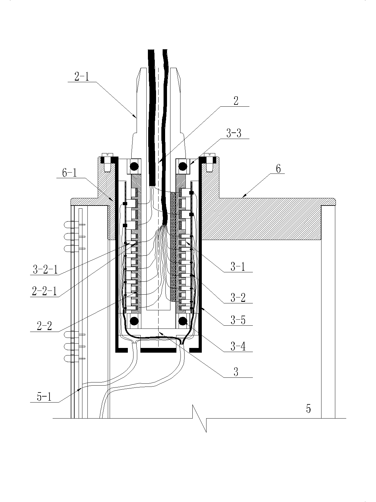
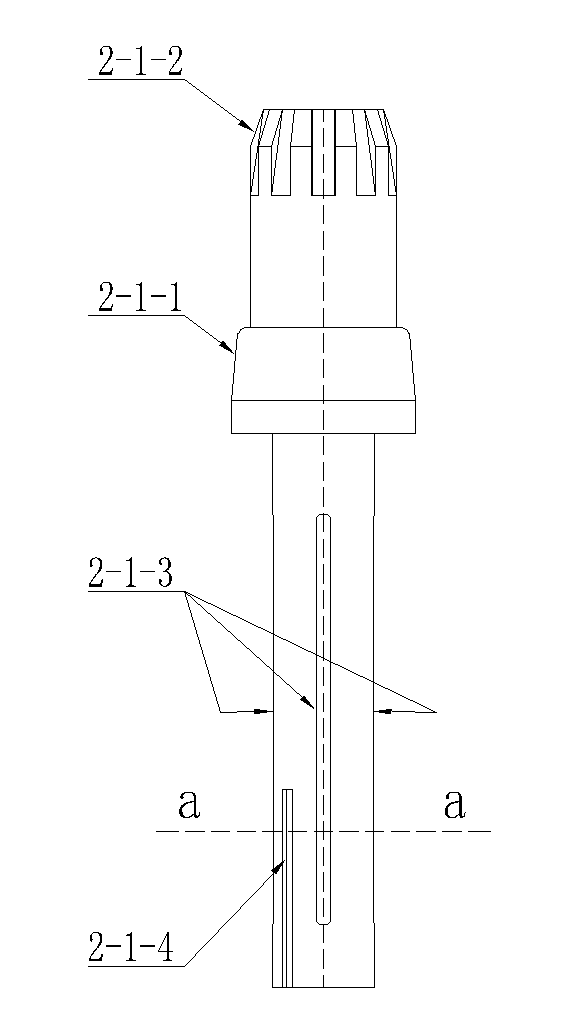
[0034] Such as figure 2 The data conducting device (1) includes a stator (2) and a rotor (3). One end of the positioning connecting shaft (2-1) is a positioning connecting end of the stator (2), and a combination is installed on the periphery of the other end Slip ring (2-2), the combined slip ring (2-2) has a data line lead to connect with external equipment; the rotor (3) is installed with a brush module inside the hollow bracket (3-1) (3-2), the brush module (3-2) also has a data cable led out to the inner cavity of the LED triangle module (5); a combined slip ring (2-2) is ...


PUM


Abstract

The invention relates to the technical field of light-emitting diode (LED) digital studio screens, in particular to an LED turnover display screen. A data conduction device comprises a stator and a rotor, wherein one end of the stator, which is located on a positioning connecting shaft, is a positioning connecting end; the periphery of the other end of the stator is provided with a combined slip ring; the combined slip ring is led out by a data line to be connected with peripheral equipment; the rotor is provided with an electric brush module at the inner side of a hollow sting; the electric brush module is also led out by a data line to an inner cavity of an LED triangular module; one end of the stator, at which the combined slip ring is arranged, is inserted into an inner cavity of the hollow sting of the rotor and is fixed, so that the combined slip ring and the electric brush module are correspondingly contacted to form information conduction between a fixed object and a rotary object; external data information is transmitted to the inner cavity of the LED triangular module through data lines; and the combined slip ring is connected with an LED display unit. The invention has the beneficial effects that the structure is reasonable; the stability is high; the service life is long; and the installation is convenient.

Description

Technical field [0001] The invention relates to the technical field of LED digital studio screens. More specifically, it relates to an LED flip display. Background technique [0002] Existing LED flip-type display screens include LED three-sided flip screens and LED two-sided flip screens. The display body is composed of multiple LED triangle modules arranged in a vertical direction, and there are decorative frames around them. The inner side plate of the decorative frame is connected, and the lower end is connected with the power driving device, which rotates according to the set law. The data information required by the rotating LED triangle module is drawn from the positioning device on the upper port through a wire and connected to an external device. Since the fixed object and the rotating object are connected by a direct wire, in order to prevent the wire from being entangled, only control can be used. Rotation angle and rotation method are used to solve the problem. The ...

Claims


Application Information

Patent Timeline
IPC IPC(8): G09F9/33
Inventor 方迪勇
Owner CHANGSHA XINYUAN ELECTRONICS TECH
Why Eureka
Try Eureka