Overall machine wind path structure of high-power and high-peed permanent magnet synchronous motor

A permanent magnet synchronous motor, high-power technology, applied in the shape/style/structure of the magnetic circuit, rotating parts of the magnetic circuit, electrical components, etc. and other problems to achieve the effect of strengthening the cooling effect, enhancing the cooling effect, and increasing the area

Inactive Publication Date: 2013-04-03
SHANGHAI DIANJI UNIV
View PDF5 Cites 9 Cited by
  • Summary
  • Abstract
  • Description
  • Claims
  • Application Information

AI Technical Summary

Problems solved by technology

like figure 1 and figure 2 As shown, in order to cool the permanent magnet motor rotor with solid pole structure, the rotor can only adopt the axial ventilation structure with holes punched in the rotor yoke
[0003] On the other hand, if image 3 As shown, in the field of high-power high-speed synchronous motors, the stator side is generally cooled by radial ventilation for the sake of ventilation and heat dissipation. Since the rotor has no radial cooling air path, in order to ensure the cooling effect of the stator side, sufficient cooling air volume is guaranteed. , can only increase the air gap ventilation area; at the same time, if the air gap ventilation area is insufficient, the eddy current loss heat on the side surface of the rotor cannot be dissipated in time, which will cause the magnet to heat up, and in severe cases, the magnet will produce irreversible demagnetization
Increase the ventilation area of ​​the air gap, that is, increase the length of the air gap, but this will increase the amount of magnetic steel, which in turn increases the manufacturing cost
[0004] On the other hand, in the field of high-power high-speed synchronous motors, such as Figure 4 As shown, although radial ventilation and axial ventilation are sometimes used at the same time, because the rotor core is long, if the rotor axial ventilation area is large, it will affect the cooling effect of air gap ventilation and affect the cooling of the stator and magnetic steel; if The small axial ventilation area of ​​the rotor will increase the wind resistance of the air path and increase the cost of external components such as coolers, which brings many restrictions to the design of high-power high-speed synchronous motors

Method used


Image

  • Overall machine wind path structure of high-power and high-peed permanent magnet synchronous motor
  • Overall machine wind path structure of high-power and high-peed permanent magnet synchronous motor
  • Overall machine wind path structure of high-power and high-peed permanent magnet synchronous motor

Examples


Embodiment Construction

[0035] The specific implementation of the air passage structure of the whole machine of the high-power and high-speed permanent magnet synchronous motor of the present invention is given below in conjunction with the accompanying drawings, but the implementation of the present invention is not limited to the following embodiments.

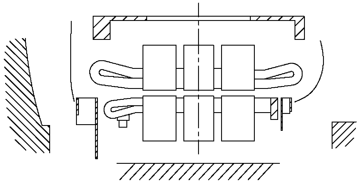
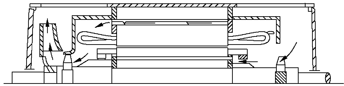
[0036] see Figure 5 . The wind path structure of the high-power high-speed permanent magnet synchronous motor includes a motor 20 and a cooler 1 that cooperate with each other. The motor 20 includes a stator 21 and a rotor 22. The stator 21 surrounds the rotor 22 with an air Gap 23. The rotor 22 comprises a rotor shaft 7 and a rotor pole 9 . The rotor pole 9 includes a permanent magnet 4 and a magnetic pole 5 . The stator 21 is provided with a radial ventilation channel 10 formed by the stator radial ventilation groove plate 8; the rotor 22 adopts a welded rib shaft structure, and the space between the welded ribs forms a waist-shaped ventilati...


PUM


Abstract

The invention discloses an overall machine wind path structure of a high-power and high-peed permanent magnet synchronous motor. The overall machine wind path structure of the high-power and high-peed permanent magnet synchronous motor comprises a motor and a cooler matched with each other, wherein the motor comprises a stator and a rotor, the stator surrounds the rotor and is provided with an air gap in the middle, the rotor comprises a rotor shaft and rotor poles, and each rotor pole comprises a permanent magnet steel and a magnetic pole. The overall machine wind path structure is characterized in that a radial air way is arranged on the stator, the rotor adopts a welding rib shaft structure, spaces between welding ribs form waist-shaped air holes, a plurality of rows of radial air holes are arranged between the rotor poles of the rotor, and axial flow fans are installed on two sides of the rotor shaft of the rotor. Whether the rotor is in a solid structure or a lamination structure, the overall machine wind path structure can prevent magnet steels from overheating partially, prevent the magnet steels from losing magnetism irreversibly and improve work reliability of the motor, and simultaneously the length of the air gap is not increased, the usage amount of the magnet steels is reduced, wind resistance of an overall machine wind path is decreased, and a need for cooling the stator fully is satisfied.

Description

technical field [0001] The invention relates to the technical field of permanent magnet synchronous motors, in particular to an air passage structure of a large-power high-speed permanent magnet synchronous motor. Background technique [0002] At present, the rotors of high-power high-speed synchronous motors are mostly laminated magnetic pole structures, and the time and cost of processing and manufacturing are relatively high. In order to reduce the time and cost of rotor processing and manufacturing, some manufacturers use solid magnetic pole structure instead of laminated magnetic pole structure, but this substitution will increase the eddy current loss on the rotor magnetic pole surface. And if there is a gap between the permanent magnets of the rotor, there will be a large repulsive force between them, which will affect the assembly of the magnetic steel. Therefore, there is generally no radial cooling air path on the rotor side, and no radial ventilation slot structur...

Claims


Application Information

Patent Timeline
Patent Type & Authority Applications(China)
IPC IPC(8): H02K9/06H02K1/32
Inventor 李全峰
Owner SHANGHAI DIANJI UNIV
Why Eureka
Try Eureka